


2-48
Cisco CRS Carrier Routing System 8-Slot Line Card Chassis Installation Guide
OL-6256-17
Chapter 2 Installing and Removing Power Components
How to Install or Remove Modular Configuration Power Components
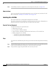
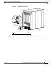
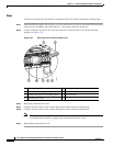
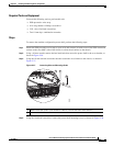
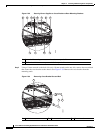
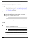
Figure 2-36 Removing Cord from Cord Clamp
Note In Figure 2-36, the AC cord clamp shown on the left was available until June 2011, and the AC
cord clamp shown on the right is available since June 2011. The location of the screw that
secures the cord in the cord clamp is different.
What to Do Next
After you remove the DC wiring and DC terminal block covers or AC cords, remove the power shelf.
See the “Removing a Modular Configuration Power Shelf” section on page 2-48.
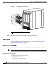
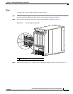
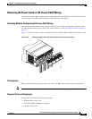
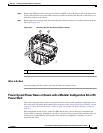
Removing a Modular Configuration Power Shelf
This section describes how to remove a modular configuration power shelf from the Cisco CRS 8-slot
line card chassis.
Although there are differences between the AC and DC power shelves, they are removed in the same
manner.
Prerequisites
Before performing this task, remove DC input power wiring or AC input cords from the shelf that you
want to disconnect. For more information, see the “Removing AC Power Cords or DC Power Shelf
Wiring” section on page 2-45.
1 Cord Clamp 3 Screw that secures the cord in clamp
2 Cord removed from clamp 4 Screwdriver that loosens screw
209331
3 4 213 4 21