


1-8
Cisco CRS Carrier Routing System 8-Slot Line Card Chassis Installation Guide
OL-6256-17
Chapter 1 Cisco CRS Carrier Routing System 8-Slot Line Card Chassis Overview
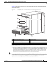
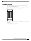
Chassis Components
• A chassis midplane that connects line cards to their associated PLIMs. The midplane design allows
a line card to be removed from the chassis without having to disconnect the cables that are attached
to the associated PLIM. The midplane distributes power, connects the line cards to the switch fabric
cards, and provides control plane interconnections. The midplane is not field replaceable by the
customer.
• One or two route processor cards (RPs). The RPs provide the intelligence of the system by
functioning as the Cisco CRS 8-slot line card chassis system controller (serving as part of the control
plane in multi-chassis systems) and providing route processing. Only one RP is required for system
operation. For redundant operation, you can order a second RP as an option (CRS-8-RP/R). When
two RPs are used, only one RP is active at a time. The second RP acts as a “standby” RP, serving as
a backup if the active RP fails.
The RP also monitors system alarms and controls the system fans. LEDS on the front panel indicate
active alarm conditions.
A Performance Route Processor (PRP) is also available for the Cisco CRS 8-slot line card chassis.
Two PRPs perform the same functions as two RPs, but provide enhanced performance for both route
processing and system controller functionality.
Note A chassis may not be populated with a mix of RP and PRP cards. Both route processor cards
should be of the same type (RP or PRP).
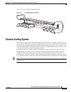
• Upper and lower fan trays. The fans pull cool air through the chassis. A removable air filter is located
below the PLIM card cage at the front of the chassis.
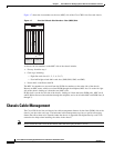
• Four half-height switch fabric cards (SFCs). These cards provide the three-stage Benes switch fabric
for the routing system. The switch fabric performs the cross-connect function of the routing system,
connecting every MSC (and its associated PLIM) with every other MSC (and its associated PLIM)
in the system.
The switch fabric receives user data from one line card and PLIM pair and performs the switching
necessary to route the data to the appropriate egress line card and PLIM pair. The switch fabric is
divided into eight planes that are used to evenly distribute the traffic across the switch fabric. Each
switch fabric card implements two planes of the switch fabric.
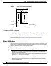
• A power system that provides redundant power to the chassis. Two types of power systems are
available: fixed configuration power and modular configuration power. Both power configurations
use either AC or DC power. The fixed configuration power solution contains two power distribution
units (PDUs), with either one AC rectifier or one DC power entry modules (PEM) per PDU. The
modular configuration power solution contains two power shelves with either up to four DC power
modules (PMs) or up to three AC PMs per power shelf.
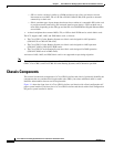
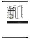
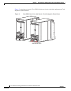
The PLIM side of the chassis is considered the front of the chassis, where user data cables attach to the
PLIMs and cool air enters the chassis. The MSC side, which is where warm air is exhausted, is
considered the rear of the chassis.