


2-31
Cisco CRS Carrier Routing System 8-Slot Line Card Chassis Installation Guide
OL-6256-17
Chapter 2 Installing and Removing Power Components
How to Install or Remove Modular Configuration Power Components
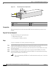
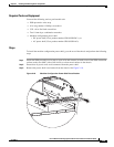
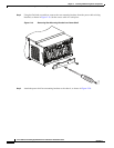
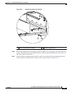
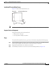
Figure 2-20 Attaching Rear Mounting Brackets
Step 6
Remove the ESD-preventive wrist strap from the rear (MSC) side of the chassis. Go to the front of the
chassis and reattach to one of the ESD connection sockets on the front (PLIM) side of the chassis or a
bare metal surface on the chassis.
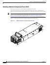
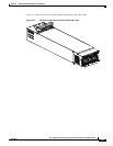
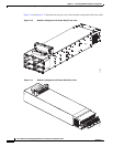
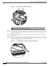
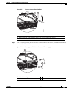
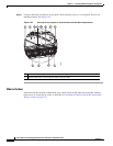
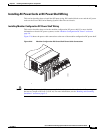
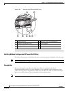
Step 7 Insert the modular configuration power shelf so that it stops against the rear mounting bracket, then
fasten the power shelf to the chassis. (There are two screws per shelf, see Figure 2-21).
1 Bolts to secure bracket to chassis 2 Wrench to tighten bolts
279999
2
1