


2-35
Cisco CRS Carrier Routing System 8-Slot Line Card Chassis Installation Guide
OL-6256-17
Chapter 2 Installing and Removing Power Components
How to Install or Remove Modular Configuration Power Components
Installing AC Power Cords or DC Power Shelf Wiring
This section describes how to install the DC input wiring, DC terminal block covers and the AC power
cords on the Cisco CRS Carrier Routing System 8-Slot line card chassis.
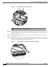
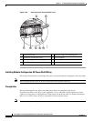
Installing Modular Configuration DC Power Shelf Wiring
This section describes how to wire the modular configuration DC power shelf. For more detailed
information on chassis DC power systems, see the “Modular Configuration DC Power” section on
page 2-9.
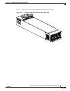
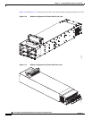
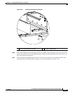
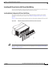
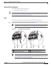
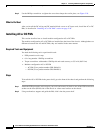
Figure 2-26 shows the power cable connections at the rear of the modular configuration DC power shelf.
Figure 2-26 Modular Configuration DC Power Shelf Power Cable Connections
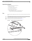
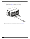
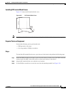
Caution When wiring the power shelf, be sure to attach the chassis ground cable to the chassis first and tighten
the nuts to a torque of 30 in-lb (3.39 N-m). For more information, see the “Bonding and Grounding
Guidelines” section on page 2-4.
281336