


2-36
Cisco CRS Carrier Routing System 8-Slot Line Card Chassis Installation Guide
OL-6256-17
Chapter 2 Installing and Removing Power Components
How to Install or Remove Modular Configuration Power Components
Prerequisites
Before performing this task, ensure that both power shelves are installed in the chassis.
Caution Before installing wiring on the power shelf, make sure that the input power cables are not energized.
Required Tools and Equipment
You need the following tools to perform this task:
• ESD-preventive wrist strap
• Crimping tool and lug specific die
• 3/8 in. ratchet wrench with 10-mm socket
• Torque wrench with 10-mm 6 pt. socket and rated accuracy at 20 in.-lb (2.26 N-m)
Steps
To wire the modular configuration DC power shelf, perform the following steps:
Step 1 Attach the ESD-preventive wrist strap to your wrist and connect its leash to one of the ESD connection
sockets on the rear (MSC) side of the chassis or a bare metal surface on the chassis.
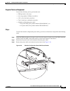
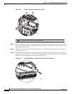
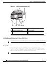
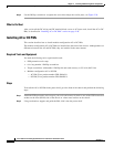
Step 2 Remove the terminal block cover.
Step 3 Use the crimping tool mandated by the lug manufacturer to crimp the lugs to the DC-input cables. For
details on lugs, see the “DC Power Systems” section on page 2-6.
The cable should be sized according to local and national installation requirements. Use only copper
cable.
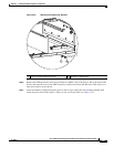
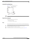
Note The power supply terminal block lug opening width is 0.63 inch (1.60 cm). The terminal posts
are centered 0.63 inches (5/8 inch) (1.60 cm) apart and are M6-threaded. We recommend that
you use an appropriately sized 180-degree (straight) or 45-degree angle industry standard
2-hole, standard barrel compression lug.
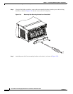
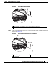
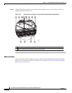
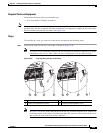
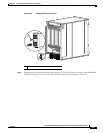
Step 4 Using the 10-mm socket wrench, attach the positive and negative cable pairs to each terminal block. Use
the torque wrench to tighten to a torque of 20 in.-lb (2.26 N-m).
Caution Make sure that the polarity of the DC input wiring is correct.
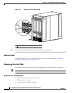
Step 5 Reattach the terminal block covers.