


2-7
Cisco CRS Carrier Routing System 8-Slot Line Card Chassis Installation Guide
OL-6256-17
Chapter 2 Installing and Removing Power Components
Power Component Information Common to Two Types of Power System
Unlike the Cisco CRS 16-slot line card chassis, the Cisco CRS 8-slot line card chassis does not contain
an alarm module. A microprocessor in the DC PEM monitors the status of each DC PEM. The
microprocessor communicates with the system controller on the route processor (RP) card. LEDs on the
front panel of the RP card indicate active alarm conditions.
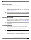
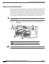
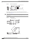
The DC PDU is shipped with a plastic safety cover over the input terminal block, as shown in Figure 2-3.
This safety cover has two parts, each part held on to the PDU with a Phillips screw. We recommend
removing the safety cover only when wiring and unwiring the chassis. The safety cover is slotted in such
a way that the cables can only come out on the bottom portion of the cover.
Figure 2-3 Fixed Configuration DC PDU with Plastic Safety Cover
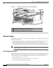
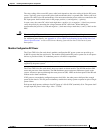
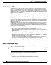
Each PDU requires three DC inputs of –48/–60 VDC (nominal), 60 A service. The PDU has three sets
of double-stud terminals (-48/-60 VDC Lines and -48/-60 VDC Returns) for connecting to the VDC inputs.
Each DC PDU should be connected to a different central office DC power source:
• One PDU should be connected to three –48/–60 VDC “A” buses.
• Other PDU should be connected to three –48/–60 VDC “B” buses.
If DC power to a PDU fails, the other PDU provides enough power for the chassis. This 2N power
redundancy enables the routing system to operate in spite of single power failure.
For DC power cables, we recommend that you use commensurately rated, high-strand-count copper
cable. These cables are not available from Cisco Systems; they are available from any commercial
vendor. DC power cables must be terminated by cable lugs at the power shelf end.
Note All six -48/-60 VDC Return input cables for one chassis should have the same cable gauges and the
lengths should be matched within 10 percent of deviation.
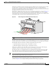
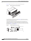
The grounding lugs should be dual-hole and able to fit over M6 terminal studs at 0.63 in (1.6 cm) centers,
as shown in Figure 2-4 (for example, Panduit part number LCD2-14A-Q, or equivalent).
1 Each set of cables (RTN and –48 V/–60 V) is a single VDC input.
129533
1