


5-4
Cisco CRS Carrier Routing System 8-Slot Line Card Chassis Installation Guide
OL-6256-17
Chapter 5 Installing and Removing Exterior Components
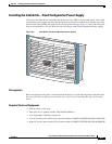
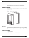
Installing or Removing the Front Side Exterior Components
Prerequisites
Be sure that no cables impede your access to the area of the chassis on which you wish to install the
bracket.
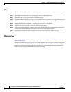
Required Tools and Equipment
You need the following tools and parts to perform this task:
• ESD-preventive wrist strap
• 6-in. long number 1 Phillips screwdriver
• Medium flat-blade screwdriver
• Cable management bracket
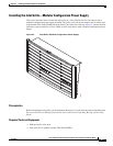
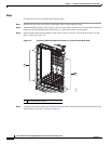
Steps
To install a cable management bracket, follow these steps:
Step 1 Attach the ESD-preventive wrist strap to your wrist and connect its leash to an ESD connection socket
or a bare metal surface on the chassis.
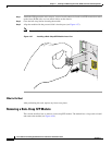
Step 2 If necessary, remove the Cisco logo bezel from the front of the chassis.
a. Gently insert the flat-blade screwdriver between the edge of the bezel and the face of the chassis and
pry the bezel loose.
The bezel is attached to the front of the chassis with four ball studs.
b. Pull the bezel firmly toward you to detach it.
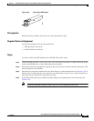
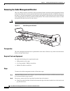
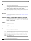
Step 3 Position the cable management bracket on the chassis.
Step 4 Insert and tighten the screws to secure the bracket to the chassis.
Tip For ease of attachment, install the inner screws first.
Caution Be careful not to damage the plastic bracket arms.
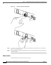
Step 5 Reattach the logo bezel by snapping it back onto the front of the chassis.
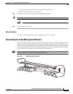
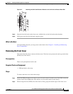
What to Do Next
Use the cable management bracket to organize your cables. Then install the inlet grille as described in
the next section.