


5-6
Cisco CRS Carrier Routing System 8-Slot Line Card Chassis Installation Guide
OL-6256-17
Chapter 5 Installing and Removing Exterior Components
Installing or Removing the Front Side Exterior Components
Steps
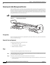
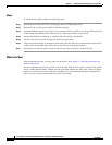
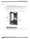
To install the inlet grille, perform the following steps:
Step 1 Remove the new inlet grille from its packaging, then set the packaging aside.
Step 2 Remove the AC rectifier power handles from their package.
Step 3 Attach the ESD-preventive wrist strap to your wrist and connect its leash to one of the ESD connection
sockets on the front (PLIM) side of the chassis or a bare metal surface on the chassis.
Step 4 Use the large Phillips screwdriver to attach the left AC rectifier power handle.
Step 5 Use the screwdriver to attach the right AC rectifier power handle.
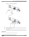
Step 6 Align and insert the hooks at the bottom of the inlet grille into the cutouts at the bottom of the chassis
casing on the front (PLIM) side of the chassis, just in front of the power modules.
Step 7 Rotate the top of the inlet grille toward the chassis, and snap it into place on the ball studs.
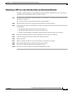
What to Do Next
After performing this task, you may power on the chassis. See Chapter 2, “Installing and Removing
Power Components.”
If you are replacing the previous version of the inlet grille with the new version, you must also replace
the AC rectifier power handles with the new ones provided with the new inlet grille. These new power
handles are necessary because the old power handles do not extend through the newly designed inlet
grille. You can do this procedure with the system still running.