


2-29
Cisco CRS Carrier Routing System 8-Slot Line Card Chassis Installation Guide
OL-6256-17
Chapter 2 Installing and Removing Power Components
How to Install or Remove Modular Configuration Power Components
Required Tools and Equipment
You need the following tools to perform this task:
• ESD-preventive wrist strap
• 6-in. long number 1 Phillips screwdriver
• 5/32 x 6-in. flat blade screwdriver
• Two 10-mm 6-pt. combination wrenches
• Modular configuration power shelf
–
DC power shelf (Cisco product number CRS-8-PSH-DC=), or
–
AC power shelf (Cisco product number CRS-8-PSH-AC=)
Steps
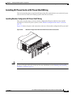
To install the modular configuration power shelf, go to the rear of the chassis and perform the following
steps:
Step 1 Attach the ESD-preventive wrist strap to your wrist and connect its leash to one of the ESD connection
sockets on the rear (MSC) side of the chassis or a bare metal surface on the chassis.
Step 2 Ensure that all power cords are disconnected from the power shelf.
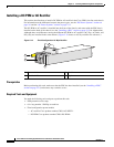
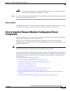
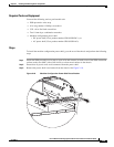
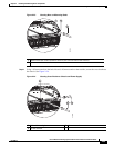
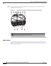
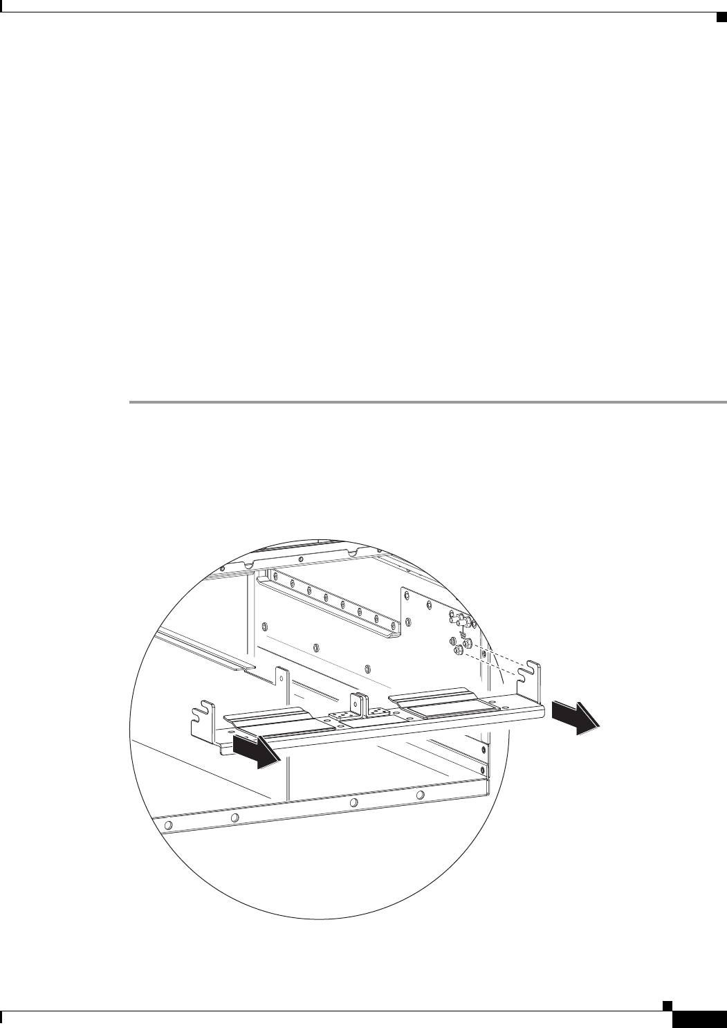
Step 3 Remove the power shelf cross bracket from the chassis. See Figure 2-18.
Figure 2-18 Modular Configuration Power Shelf Cross Bracket
254849