


2-9
Cisco CRS Carrier Routing System 8-Slot Line Card Chassis Installation Guide
OL-6256-17
Chapter 2 Installing and Removing Power Components
Power Component Information Common to Two Types of Power System
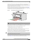
The color coding of the source DC power cable leads depends on the color coding of the site DC power
source. Typically, green or green and yellow indicates that the cable is a ground cable. Follow your local
practices for cable color code and markings. You must ensure that the power cables are connected to the
DC-input power shelf terminal studs in the proper positive (+) and negative (–) polarity.
In some cases, the source DC cable leads might have a positive (+) or negative (–) label, but you must
verify the polarity by measuring the voltage between the DC cable leads. When making the
measurement, the positive (+) lead and negative (–) lead must always match the (+) and (–) labels on the
PDU.
Caution When installing DC power cables, make sure that the polarity of the DC input wiring is correct.
For additional power details, see Appendix A, “Cisco CRS Carrier Routing System 8-Slot Line Card
Chassis Specifications” or Cisco CRS Carrier Routing System 8-Slot Line Card Chassis System
Description.
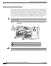
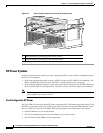
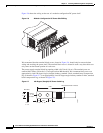
Modular Configuration DC Power
The Cisco CRS 8-slot line card chassis modular configuration DC power system can provide up to
8,400 W to power the line card chassis. The modular configuration DC power system uses A or B power
shelves to provide reliable, 2N redundant power to all chassis components.
Note Depending on the hardware deployed at your site, your system may not consume the maximum power
supplied by the power system.
The Cisco CRS 8-slot line card chassis does not contain an alarm module. The DC PM monitors PM
status and processes alarm functions. The PM distributes power and passes PM status signals to the
system. Alarms are processed through the route processor (RP). LEDs on the front panel of the RP card
indicate active alarm conditions.
If DC power to one modular configuration power shelf fails, the other power shelf provides enough
power for the chassis. This 2N power redundancy enables the routing system to operate in spite of single
power failure.
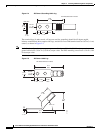
Each power shelf operates with up to four DC inputs of –48/–60 VDC (nominal), 60 A. The power shelf
accepts input DC power in the range –40 to –72 VDC.