


Multipoint Wireless Support for the Cisco uBR7200 Series Universal Broadband Router
show interface radio led
130
Cisco IOS Release 12.1(5)XM
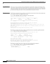
show interface radio led
To display the status of light-emitting diodes (LEDs) on the wireless modem card, and to display the
events related to the major and minor LEDs, use the show interface radio led EXEC command.
show interface radio slot/port led [major-events | minor-events]
Syntax Description
Defaults No default behavior or values.
Command Modes EXEC
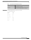
Command History
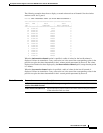
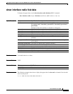
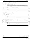
Usage Guidelines Table 2 lists the LEDs and their functions for the multipoint fixed wireless modem card:
slot/port Specifies the slot and upstream port numbers of the wireless modem card.
major-events Lists any major event that occurred in the system.
minor-events Lists any minor event that occurred in the system.
Release Modification
12.1(3)XQ1 This command was introduced.
Table 2 show interface radio led Field Description
LEDs Function
Enabled When green, it indicates that the wireless modem card is on,
receiving power from the router midplane, and enabled for
operation. This LED remains on during normal operation of the
Cisco uBR7200 series router.
Major alarm When yellow, it indicates that a major alarm has occurred in the
radio subsystem. The link is down.
Minor alarm When yellow, it indicates that a minor error occurred in the radio
subsystem. The link is degraded and might need maintenance
action, or one or more user-defined event thresholds have been
exceeded.
Out of service Identifies the service availability of the radio link. When yellow,
it indicates that the radio link is up, but not available for use
(typically during a test or loopback mode). If there is no light, it
indicates that service is permitted.
Carrier Identifies the state of the radio link. When green, it indicates that
the radio link is synchronized and the line protocol is up. When
yellow, it indicates that the radio link is not in synchronization.