


Multipoint Wireless Support for the Cisco uBR7200 Series Universal Broadband Router
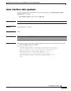
show radio flap-list
151
Cisco IOS Release 12.1(5)XM
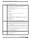
Insertions (Ins) Link insertion is the process whereby a modem performs an initial maintenance procedure to establish
a link with the headend. The Ins column is the flapping modem’s insertion count and indicates the
number of times the RF link was abnormally reestablished. An abnormality is detected when the time
between link reestablishment attempts is less than the user-configurable parameter.
Normal modem activity follows the sequence below:
1. The initial link insertion is followed by a keepalive loop between the headend and radio modem
and is called station maintenance.
2. Power on
3. Initial maintenance
4. Station maintenance
5. Power off
When the link is broken, initial maintenance is repeated to reestablish the link:
1. Initial maintenance time T1
2. Station maintenance
3. Init maintenance at time T2
The Ins and Flap counters in the flap list are incremented whenever T2 – T1 < N, where N is the
insertion-time parameter configured by the radio flap-list insertion-time command. Default value for
this parameter is 180 seconds.
A high Ins number indicates:
• Intermittent downstream sync loss
• Dynamic Host Configuration Protocol (DHCP) or modem registration problems
Hit and Miss The hit and miss columns are keepalive polling statistics between the Cisco uBR7200 series and the
radio modem. The station maintenance process occurs for every modem approximately every 25
seconds. When the headend receives a response from the modem, the event is counted as a hit. If the
headend does not receive a response from the radio modem, the event is counted as a miss. A radio
modem fails to respond either because of noise or if it is down. Modems that only log misses and zero
hits are assumed to be powered off.
Misses are not desirable, because they are usually an indication of a upstream problem; however, having
a few misses is normal. The flap count is incremented if there are M consecutive misses where, M is
configured by the radio flap miss-threshold command. The parameter value ranges from 1 to 12, with
a default of 6.
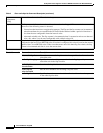
Ideally, the hit count should be much greater than the miss counts. If a modem has a hit count much
less than its miss count, then registration is failing. Noisy links cause the miss/hit ratio to deviate from
a nominal 1 percent or less. High miss counts can indicate:
• Intermittent upstream, possibly due to noise
• Too much or too little upstream attenuation
Cyclical
RedundancyCheck
(CRC)
This statistic tracks the CRC error counter per modem. CRC errors are usually an indication of noise
on a plant. A low count can be always be expected, but a high CRC number calls for plant
troubleshooting. The CRC counter indicates:
• Intermittent upstream
• Impulsive noise or interference
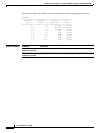
Table 3 Show radio flap-list Command Description (continued)