Multipoint Wireless Support for the Cisco uBR7200 Series Universal Broadband Router
Feature Overview
3
Cisco IOS Release 12.1(5)XM
Multipoint Headend Components
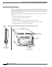
Router
The Cisco uBR7200 series are designed for two-way transmission of digital data using either coaxial
cable or broadband fixed wireless signals. These routers support IP routing with a wide variety of
protocols and any combination of Ethernet, Fast Ethernet, High-Speed Serial Interface (HSSI), serial,
and Asynchronous Transfer Mode (ATM) media. Network interfaces reside on port adapters that
provide the connection between the router and external networks. Cable or wireless interfaces reside on
modem cards and provide the connection to cable or wireless networks.
Other features include:
• Online insertion and removal (OIR)—Add, replace, or remove a port adapter and modem cards
without interrupting the system or entering any console commands
• Downloadable software—Load new images into Flash memory remotely, without having to
physically access the router
For further information regarding the Cisco uBR7200 series, including detailed installation and
configuration instructions, refer to the Cisco uBR7200 Series Universal Broadband Router Installation
and Configuration Guide.
Wireless Modem Card
The wireless modem card installs in a modem card slot of a Cisco uBR7200 series. It is configured
through the router’s system console or via the CiscoView network management system. The wireless
modem card provides the control and data interface to the system’s digital motherboard and the radio
frequency (RF) subsystem in the wireless transverter. It also provides the up/down conversion from
baseband to intermediate frequency (IF).
The wireless modem card consists of the following components:
• Digital motherboard
• IF analog board
• 10-MHz input connection for external reference clock signal (external reference clock is optional)
• 10-MHz output connection for forwarding optional external reference clock signal to another
wireless modem card
• Monitor connections for monitoring the power feed panel connections (main and diversity)
• Power feed panel connections (main and diversity)
• Light-emitting diodes (LEDs) that provide a visual indication of the state of the modem card
For further information regarding the wireless modem card, including detailed installation and
configuration information, refer to the Cisco uBR7200 Series Router Multipoint Wireless Modem Card
and Subsystem Installation document.
Power Feed Panel
The power feed panel serves as an interconnection device between the wireless modem card, the
wireless transverter, and a –48 VDC power supply. The main purpose of this unit is to provide
DC power to the system, provide control signals to the wireless transverter, and transmit and receive IF
signals to and from the transverters. In addition, the unit contains circuit breakers for the DC power.


