Configuration Extensions
106
372 SPU 780 01EMAN May 2002
Quantum Hot Standby
Overview The Quantum Hot Standby extension allows additional configuration of the Quantum
Hot Standby setup. This lets you set the type of state RAM transfer between the
CHS110-00 modules. It also lets you set the Initial Command Register and the Non-
Transfer Area.This area is only available on version 2.x Quantum controllers that
contain the CHS loadable in the configuration.
Editing the
Quantum Hot
Standby
Extension
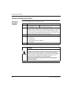
In the Active Extensions panel select the Quantum Hot Standby extension, then:
Note: If the Quantum Hot Standby extension does not appear in the Active
Extensions panel, it is not a valid extension for the current controller type.
Step Action
1 In the General tab, enter the 4xxxx address of the command register used to
configure the hot standby system in the Command Register field. This register
must be transferred every scan and cannot be in the non-transfer area.
The initial command register contains the settings that are loaded into the
controller when it is started. If any changes need to be made while the controller
is running, the command register must be used, and not the initial command
register. Settings such as port address swapping, allowing an executive
upgrade, setting the standby’s mode on a logic mismatch, setting the controller’s
modes and overriding the key switch can be changed from the command
register.
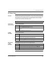
2 Enter the starting address of the range of registers that are not to be transferred
from the primary controller to the standby in the Non-Transfer Area Start
Address field. This is commonly used to reduce scan time.
The first two registers are used in reverse transfer operations. These
registers allow information to be passed from the standby to the primary
controller.
The third register is the Status register, which stores the status of both
controllers. This register provides information on how the hot standby system
is operating, such as the power flow of the CHS instruction, position of the
controller’s A/B switch, and whether there is a logic mismatch between
controllers.
All registers following the third register are ignored (not transferred) during
the scan.
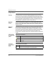
3 Enter the length of the non-transfer register range in the Non-Transfer Area
Length field. This value can be from 1 through the total number of registers
configured in the controller.


