Configuring a Controller
82
372 SPU 780 01EMAN May 2002
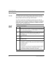
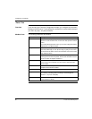
ASCII Ports This table allows the user to set each port to be compatible with the device to which
it is being connected.
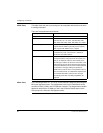
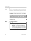
There are five properties that can be set:
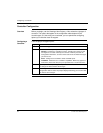
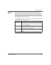
Micro Ports If you are using a Micro 311, 411, 512, or 612 controller, assign it’s ports using the
Micro port drop-down menu. The assignments in the list are combinations of the
controller’s COM1, COM2, and I/O Expansion Link port. The assignments available-
depend on which Micro I/O Mode you set in the Controller Details section of the
General tab in the Controller Configuration editor.
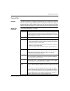
Property Description
Parity Select EVEN, ODD, or NONE.
Baud Rate The communication speed is set to one of the following
baud rates: 50, 75, 110, 134.5, 150, 300, 600, 1200,
1800, 2000, 2400, 3600, 4800, 7200, 9600, and 19200.
Number of Stop Bits Select the number of stop bits for each data byte (1 or 2).
A system with NO PARITY generally uses 2 stop bits,
while a system with PARITY uses 1 stop bit.
Number of Data Bits Select the number of data bits issued from the ASCII port
(a number from 5 to 8). The choice of 7 data bits is
standard for most ASCII devices.
Keyboard/Non-Keyboard Select the attached device is defined as a keyboard or
non-keyboard device. The purpose of this function is to
allow you to modify the response of the ASCII port to
match the type of device to which it is connected. In the
keyboard mode, the port echoes back the input character
and requires delimiters to move to the next data field and
to terminate the message. Editing of input data is
possible from a terminal. In the non-keyboard mode, no
data is echoed back and, as a data field is completed, the
next available data field is entered or the message
automatically terminates. No editing capabilities are
supported.


