Configuring a Controller
372 SPU 780 01EMAN May 2002 77
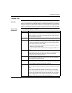
‘General’ Tab
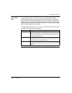
Overview This tab in the Controller Configuration window allows you to configure a controller’s
memory. It contains many important options, including the number of coils, registers,
segments of logic, and I/O cards the controller will use, the amount of memory it sets
aside for configuration extensions, and the number and size of its ASCII messages.
General Tab
Parameters
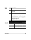
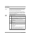
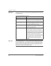
The following parameters are editable:
Parameter Description
Registers For each of the 0xxxx, 1xxxx, 3xxxx, and 4xxxx register fields, type the
number of registers the controller will use. The controller polls all of these
registers each scan, so to keep your controller scanning quickly, set up only
as many registers as you need.
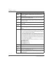
Segments Type the number of logic segments the controller will use.
I/O Drops Different controllers use different I/O drops:
If you have a controller that uses Channels instead of I/O Drops, type the
number of channels the controller I/O will use. Channels always come in
pairs, so this must be an even number.
If you have a Micro series controller in parent mode, type the number of
children (0 to 4) associated with it.
If you have a Micro series controller in child mode, type the Child ID (1 to
4).
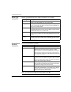
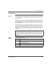
I/O Words Quantum, Atrium, 785E_LMS, Momentum, Compact (E258, E265, E275,
E258) controllers only: type the maximum number of I/O words that will be
available for programming in the Traffic Cop. Check your controller
documentation for the appropriate values.
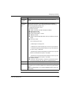
DCP Drop ID 680, 685, 685E, 780, 785, 785E or 785L controllers only: If another computer
uses this controller for distributed control, type the controller’s Distributed
Control Processor ID number (0 to 32).
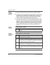
I/O Time Slice Type the amount of time the controller will devote to peripheral port
communication, from 1 to 100 milliseconds. The default is 10 ms for 984A,
B, and X controllers and 20 ms for Quantum controllers.
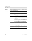
Duplicate Coil
Start
Set the starting address to a non-zero value to enable the duplicate coil
range (i.e. allow coil addresses within this range to be assigned to more than
1 coil).
Set the range to 0 disable the duplicate coil address range. The starting
address of the duplicate coil range is part of the configuration and defines
the entire range of coils that will be treated as duplicate coils. The range is
from the starting address to the configured number of coils. Therefore to
enable the entire range of coils, set the starting address to 1.


