


Performance Verification
AWG710 Service Manual
4-17
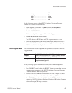
Source . .................... CH1
Coupling .................... DC
Slope ...................... Positive
Level ...................... +100 mV
Mode . ..................... Auto
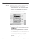
Do the following steps to set the AWG710 Arbitrary Waveform Generator
controls and to select the waveform file:
1. Push UTILITY (front-panel)!System (bottom)!Factory Reset
(side)!OK (side).
2. Load the MODE.WFM file.
Refer to Loading Files on page 4–10 for file loading procedures.
3. Push the RUN and CH1 output buttons.
The LEDs above the RUN button and CH1 output connectors are on.
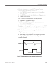
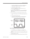
4. Check that the amplitude of the sine wave displayed on the oscilloscope is
five vertical divisions and that a waveform of approximately one cycle per
2.5 horizontal divisions is displayed.
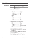
The following table lists the equipment and prerequisites required to check the
Triggered mode.
Equipment
required
Two 50ĂW BNCĂcoaxial cables, aĂ50ĂW SMAĂcoaxial cable,
aĂSMA(Fe)ĆBNC(Ma)Ăadapter,ĂaĂBNCĆTĂ(male to 2 females) adapter , a
function generator, and an oscilloscopeĂ(TDS784D).
Prerequisites The AWG710 Arbitrary Waveform Generator must meet the
prerequisites listed on page 4-8.
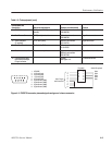
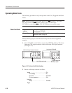
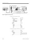
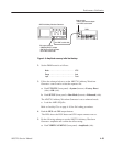
Do the following steps to install the test hookup and set the test equipment
controls:
1. Use a 50
ĂW BNC coaxial cable and a BNC-T adapter to connect the function
generator output connector to the AWG710 Arbitrary Waveform Generator
TRIG IN connector. Refer to Figure 4–6.
2. Connect a second 50
ĂW BNC coaxial cable to the BNC-T adapter. Connect
the opposite end of the coaxial cable to the oscilloscope CH2 input.
3. Use a 50 W SMA coaxial cable
and SMA (female)-BNC (male) adapter to
connect the AWG710 Arbitrary Waveform Generator CH1 output connector
to the oscilloscope CH1 input connector.
Check Triggered Mode