


Performance Verification
4-36
AWG710 Service Manual
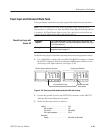
4. Load the PULSE.WFM file.
Refer to Loading Files on page 4–10 for file loading procedures.
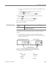
5. Push the RUN and CH1 output buttons.
The LEDs above the RUN button and CH1 output connector are on.
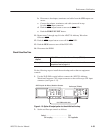
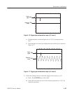
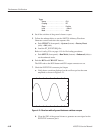
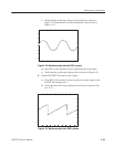
6. Verify the pulse response at 1 V amplitude.
a. Verify that the rise time of the waveform displayed on the oscilloscope
from 10% to 90% point is equal to or less than 480 ps.
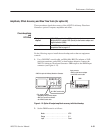
7. Do the following substeps to change the connection to check the CH1
:
a. Push the CH1 output button.
b. Disconnect the cable from the CH1 output connector.
c. Connect the cable to the CH1
output connector.
d. Push the CH1
output button to turn on the CH1 LED.
8. Repeat the Check Pulse Response procedure for the AWG710 Arbitrary
Waveform Generator CH1
.
9. Push the CH1
output button to turn off the CH1 LED.
10. Disconnect the oscilloscope.