


Performance Verification
AWG710 Service Manual
4-19
6. Follow the substeps below to set the AWG710 Arbitrary Waveform
Generator controls and to select the waveform file:
a. Push UTILITY (front-panel)!System (bottom)!Factory Reset
(side)!OK (side).
b. Push SETUP (front-panel)!Run Mode (bottom)!Triggered (side)
c. Load the MODE.WFM file.
Refer to Loading Files on page 4–10 for file loading procedures.
d. Push the RUN and CH1 output buttons.
The LEDs above the RUN button and CH1 output connectors are on.
e. Push the FORCE TRIGGER button.
Verify that the oscilloscope displays a one-cycle sine wave when the FORCE
TRIGGER button is pushed. You may need to adjust the horizontal position
control to see the signal.
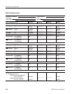
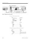
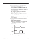
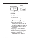
7. Follow the substeps below to check the triggered mode with external
triggering:
a. Turn on the function generator output.
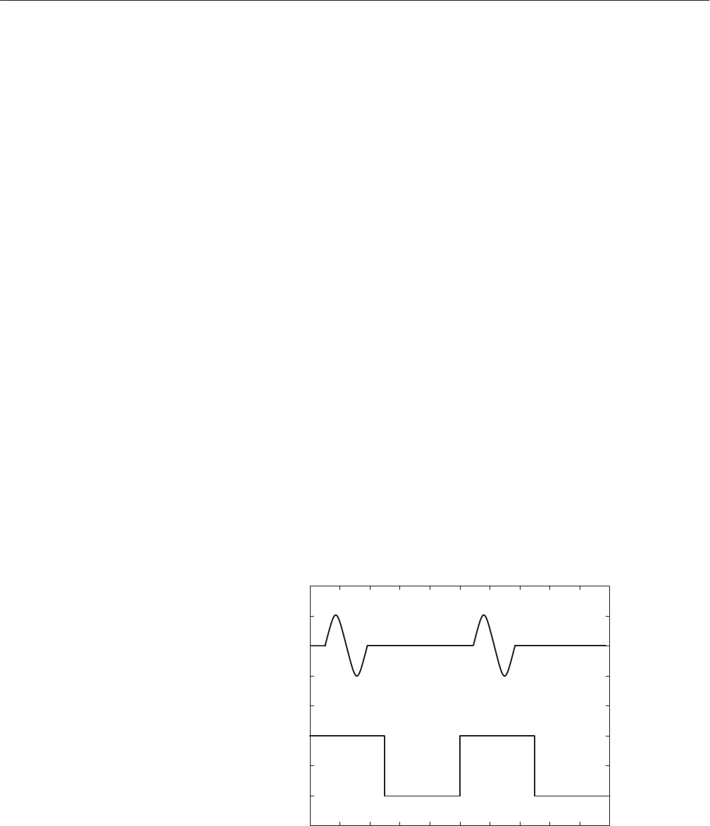
b. Verify that the oscilloscope displays a one-cycle sine wave for each
trigger supplied by the function generator. See Figure 4–7.
Retain the test hookup.
Waveform
output
CH1
Trigger
signal
CH2
Figure 4-7: Relationship between trigger signal and waveform output