


Removal and Installation Procedures
6-42
AWG710 Service Manual
You will need a screwdriver with a size #2
Phillips tip (Table 6–4, Items 1 and
3).
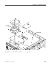
1. Locate the modules to be removed in Figure 6–3, page 6–13.
2. Do the PS100 Low Voltage Power Supply procedure (page 6–34) to remove
the power supply module.
3. Install the front cover (optional accessory) if it is not already installed.
4. Orient the waveform generator so the bottom is on the work surface and the
rear is facing you.
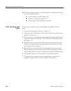
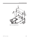
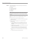
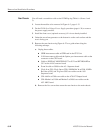
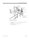
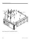
5. Remove the rear chassis using Figure 6–22 as a guide when doing the
following substeps:
a. Unplug these cables:
H GPIB interconnect cable at GPIB card in the CPU Unit
H LAN interconnect cable and the Option port interconnect cable at the
connector on the CPU board
H Cable to DISPLAY MONITOR OUT at J152 and KEYBOARD at
J112 on the A10 Connector board
H Event In cable at J1000 on the A5– Sequence board
H Clock In at J210, Clock Out at J700, 10MHz Ref In at J500, 10MHz
Ref Out at J530, and Trig In at J300 coax cables on the A50
Sequence board
H CHx Add In at J300 coax cable on the A70/A72 Output board
H CHx Marker1 at J1004 and Marker2 at J1006 coax cables on the
A52 AWG board
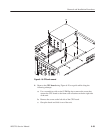
b. Remove the five screws that secure the rear chassis to the main chassis.
Rear Chassis