


Removal and Installation Procedures
6-34
AWG710 Service Manual
10. See the following procedures, in the order shown, to complete the reassemb-
ly of the waveform generator:
H A20 Front Panel Assembly (page 6–24)
H Trim Ring, Menu Buttons (page 6–23)
H Cabinet (page 6–20) (completes reassembly)
You will need a screwdriver with a size #2 Phillips tip (Table 6–4, Items 1
and 3).
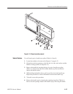
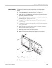
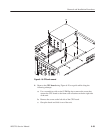
1. Locate the Power Supply in Figure 6–3, page 6–13.
2. Orient the waveform generator so the bottom is on the work surface and the
right side is facing you.
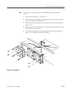
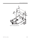
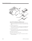
3. To remove the low-voltage power supply, unplug four power cables from J3
on the A10 Connector board and J1, J2, and J4 on the A50 Sequence board.
See Figure 6–17.
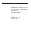
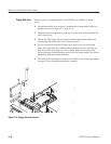
4. Remove the two screws on the left side of the rear Principal Power switch
and the power cable connector of the generator that mount the low-voltage
power supply to the rear chassis.
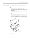
5. Remove the four screws from the top of the supply, the five screws at the
bottom, and the one screw from the side that mounts the supply to the main
chassis. Then remove the screw securing the ground lead to the main chassis.
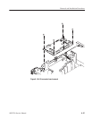
6. Lift the module up and out of the generator to complete the removal.
7. To install, do this procedure in reverse order then refer to the Cabinet
procedure, on page 6–20 to complete assembly of the generator.
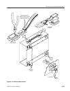
PS100 Low Voltage Power
Supply