


Performance Verification
4-50
AWG710 Service Manual
Marker Output Tests
The following procedures check the accuracy of the AWG710 Arbitrary
Waveform Generator marker output level.
NOTE. Connect a 50 W SMA terminator to the inverted marker output connector
during the marker output tests.
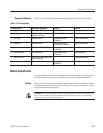
Equipment
required
A 50ĂW BNCĂcoaxial cable, a 50ĂWĂprecision terminator, aĂSMA
(male)ĆBNC (female)Ăadapters, BNC (female)ĆtoĆdual banana adapter,
and a digital multimeter (DMM).
Prerequisites The AWG710 Arbitrary Waveform Generator must meet the
prerequisites listed on page 4-8.
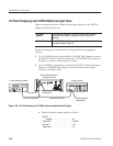
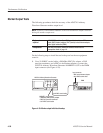
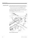
Do the following steps to install the test hookup and set the test equipment
controls:
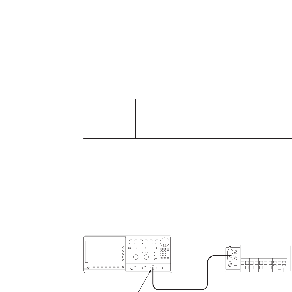
1. Use a 50 W BNC coaxial cable, a SMA(Ma)-BNC(Fe) adapter, a 50 W
precision terminator, and a BNC-to-dual banana adapter to connect the
AWG710 Arbitrary Waveform Generator MARKER 1 OUT to the DMM
input connector (see Figure 4–29).
DMM
50 W BNCĂcoaxial cable
InputĂconnector
+ĂBNCĆtoĆdual banana adapter
+Ă50 W BNCĂcoaxialĂcable
AWG710 Arbitrary Waveform Generator
MARKER 1ĂoutĂconnector
+ĂSMA(Male)ĆBNC(Female) adapter
+ĂBNC 50 WĂprecision terminator
+Ă50 WĂBNC coaxial cable
Figure 4-29: Marker output initial test hookup