


Removal and Installation Procedures
6-32
AWG710 Service Manual
You will need as screwdriver with a size #1 Phillips tip (Table 6–4, Items 1
and 2).
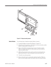
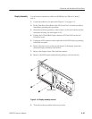
1. Locate the modules to be removed, including those listed under Additional
Modules Removed in Figure 6–3, page 6–13.
2. Orient the waveform generator so the top is on the work surface and the left
side is facing you.
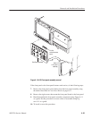
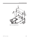
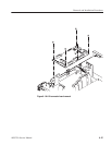
3. Unplug the J102 floppy driver connector (ribbon interconnect cable) that
connects the disk drive to the A10 Connector board.
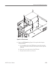
4. Use the screwdriver with a #1 Phillips tip to remove the two screws that
secure the floppy disk drive with bracket to the main chassis, and lift it out
from the chassis using Figure 6–15 as a guide. When removing the disk
drive main body from the bracket, remove the screw that secures the drive to
the bracket, then pull out the disk drive.
5. To install, do this procedure in reverse order. Refer to the Cabinet procedure
on page 6–20 to complete the generator assembly.
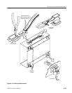
J102
Figure 6-15: Floppy disk drive removal
Floppy disk drive