


Removal and Installation Procedures
6-10
AWG710 Service Manual
The Replaceable Mechanical Parts section lists all modules.
The following procedures are described in the order in which they appear in this
section.
H The Accsess Procedure on page 6–16 directs you to the procedure(s) (if any)
that are required to access the module to be serviced, then it directs you to
the procedure to remove that module.
H Procedures for External Modules on page 6–17 explain how to remove
modules that do not require internal access to the waveform generator.
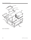
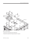
H Procedures for Internal Modules (1) on page 6–30 are procedures for
removing modules which require access to the internal part of the waveform
generator but are external to the chassis.
H Procedures for Internal Modules (2) on page 6–44 are procedures for
removing modules which require access to the internal part of the waveform
generator and are internal to the chassis.
Equipment Required. Most modules in this generator can be removed using a
screwdriver with a size #2, Phillips tip. Use this tool whenever a procedure step
instructs you to remove or install a screw unless a different size screwdriver is
specified in that step. All equipment required to remove and install a module are
listed in the first step of each procedure.
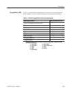
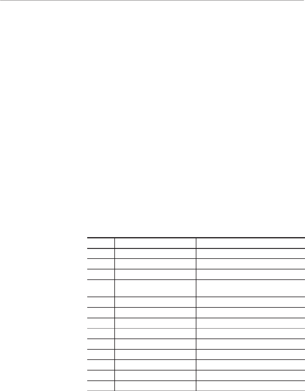
Table 6-4: Tools required for module removal
Item no. Name Description
1 Screwdriver handle Accepts PhillipsĆdriver bits
2 #1 Phillips tip PhillipsĆdriver bit for #1 screw size
3 #2 Phillips tip PhillipsĆdriver bit for #2 screw size
4 FlatĆblade screwdriver Screwdriver for removing standard-headed
screws
5 NeedleĆNose Pliers Standard tool
6 Nutdriver,
1
@
2
inch Standard tool
7 Nutdriver, 5.5 mm (7/32 inch) Standard tool
8 Nutdriver, 7 mm (9/32 inch) Standard tool
9 Retaining Ring Pliers Standard tool
10 AngleĆTip Tweezers Standard tool
11 Soldering Iron Standard tool
12 Pliers Standard tool
13 Solder Wick Standard tool
List of Modules
Summary of Procedures