


Removal and Installation Procedures
AWG710 Service Manual
6-47
You will need a screwdriver with a size #2 Phillips tip (Table 6–4, Items 1 and 3)
and a nutdriver 5.5 mm (Table 6–4, Item 7).
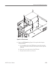
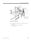
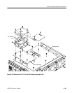
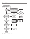
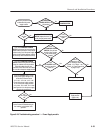
1. Locate the modules to be removed in Figure 6–5, page 6–15.
2. Orient the waveform generator so the top is on the work surface and the rear
is facing you.
3. Perform the A77 Attenuator Board and A72 Output Board procedures prior
to this procedure to remove the Sequence board.
4. Unplug the following cables and connectors:
H Three power supply cables J610, J630 and J670
H Flat cable from Event Input at J560
H Flat cable from A22 On/Off board at J600
H Two flat cables from PCI Interface board at J100 and J110
H Coax cables from 10MHz Ref Out at J5230, 10MHz Ref In at J5210, 1/4
Clock Out at J5450 and Trigger In at J5100
H Four coax cables from Marker Out at J5510, J5511, J5610 and J5611
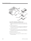
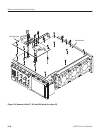
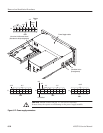
5. Remove the A50 AWG board using Figure 6–23 on page 6–45 as a guide.
a. Remove the six spacer posts.
b. Remove the eight screws that attach the Sequencer board to the main
chassis.
6. To install, do the procedure in the reverse order.
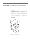
A50 AWG Board
(A common circuit board)