


Specifications
AWG710 Service Manual
1-9
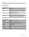
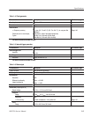
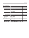
Table 1-11: Auxiliary inputs
Characteristics Description PV reference page
Trigger input
5
Connector Rear panel BNC connector
Impedance 1kW or 50 W
Polarity (Trigger mode)/Slope
(Gated mode)
POS (positive) or NEG (negative)
Input voltage range
"10V,intoa1kW load
"5V,intoa50W load
Threshold
Level -5.0 V to 5.0 V
n Accuracy
"5% of level " 0.1 V
Page 4-37
Resolution 0.1 V
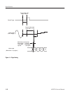
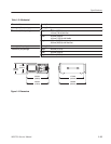
Triggered mode See Figure 1-1.
Minimum pulse width 10 ns, 0.2 V amplitude
Trigger holdoff time
x 109.5 clocks + 500 ns
Delay to analog out, Typical 211.5 clocks + 17 ns (Output: Norm, Filter: Through)
Gated mode
Minimum pulse width 1152 clocks + 10 ns, 0.2 V amplitude
Gate holdoff time
x 1920 clock + 20 ns
Delay to analog out, Typical (1335 to 1499.5) clocks+9ns(Output: Norm, Filter: Through)
5
The characteristics are specified at the end of the BNC cable (012Ć0482Ć00).