


Removal and Installation Procedures
6-26
AWG710 Service Manual
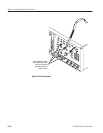
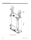
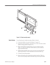
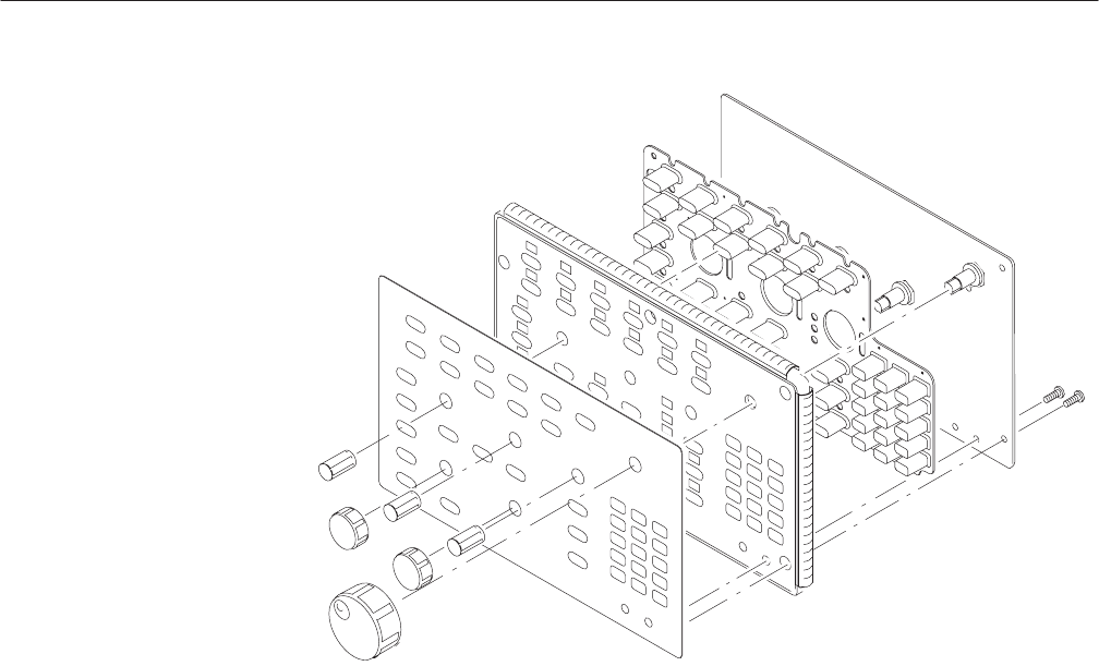
Figure 6-11: Disassembly of front panel assembly
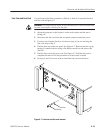
You will need a screwdriver with a size Phillips #2
tip (Table 6–4, Items 1
and 3).
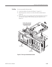
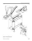
1. Locate the modules to be removed in Figure 6–2, page 6–12.
2. Do the Trim Ring and A20 Front panel assembly procedures immediately
preceding this procedure.
3. Orient the waveform generator so the bottom is on the work surface and the
front is facing you.
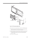
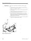
4. To remove the output panel, disconnect the on/off cable at J200 of the A50
AWG board and all the Analog output cables at J190 and J290 of each
A70/A72 Output boards.
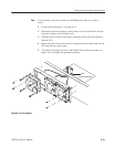
5. Remove the three screws at the front side of the chassis, the two screws on
the bottom of the chassis and the two screws at the right side of chassis
attaching the Output assembly to the main chassis.
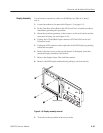
6. Pull out the Output assembly from the main chassis.
7. To install, reverse this procedure.
Output Assembly