


Operating Basics
2-14
AWG710 Service Manual
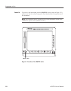
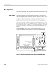
See Figure 2-5
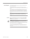
See Figure 2-4
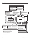
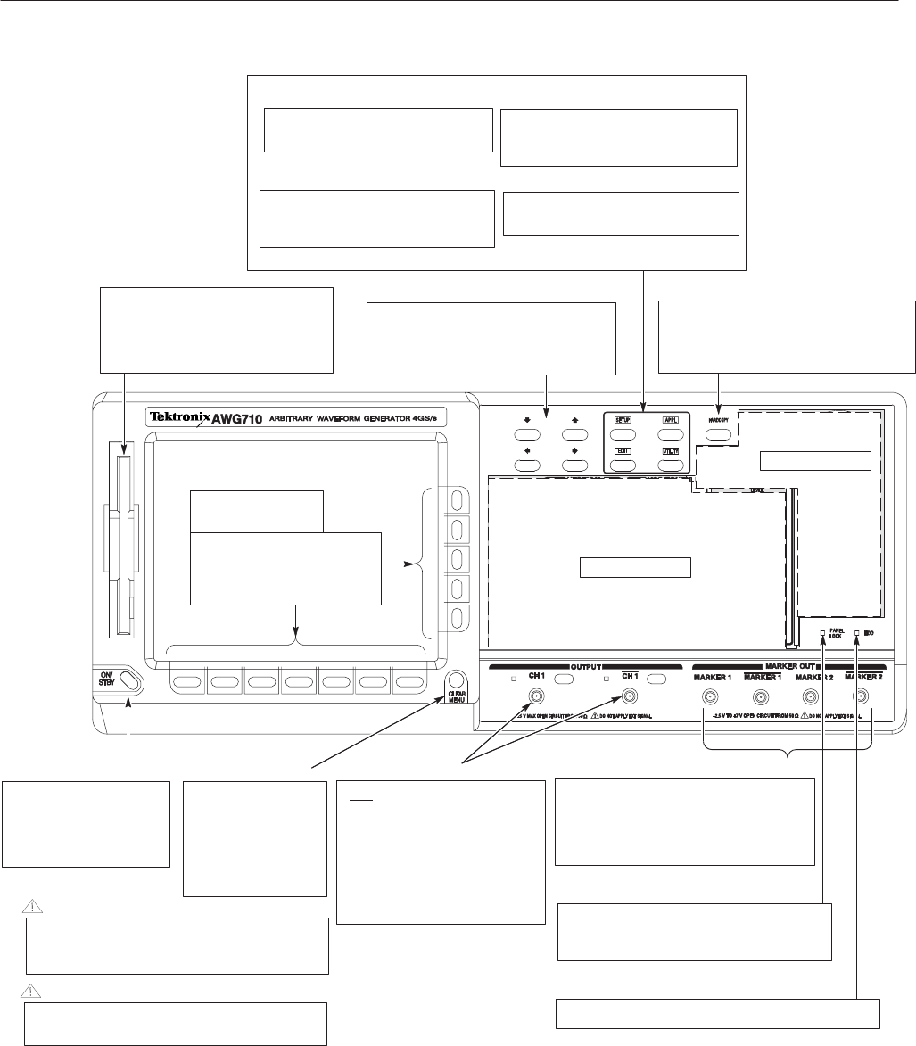
CLEAR MENU button
Bottom and side
bezel menu buttons
The bottom buttons call up
submenu, and the side buttons
execute more detailed operations
within the submenu.
Cancels the current
operation and closes
the side and submenu.
The display can be
returned to the top level
by pushing this button
repeatedly.
Arrow buttons
Controls up, down, right, and left
movements of the cursor or a selected item;
for example, movements of a selected item
in a dialog box or popĆup menu.
Floppy disk drive
Save or load the various types of data
created or used in the instrument to/from
the 3.5 inch 2HD floppy disk with
MSĆDOS format. You can also format a
floppy disk with this instrument.
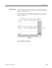
UTILITY menu button
SETUP menu button
Displays the SETUP Main Menu for
setting the waveform output parameters.
EDIT menu button
Displays the EDIT Main Menu for
creating or editing waveforms, as well as
performing directory and file tasks.
APPL menu button
Displays the APPL Main Menu for running
a specific application program to create
waveforms.
Displays the UTILITY Main Menu for
setting the instrument parameters.
HARDCOPY button
Produces a hardcopy of the screen display,
which can be transferred, as a file, to the
hard disk, a floppy disk, and/or a networked
device.
HDD LED indicator
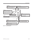
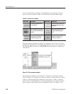
Output connectors
MARKER OUT connectors
Outputs marker signals. Each channel is
equipped with two MARKER OUT connectors.
If you use only one output connector for each
marker, you must terminate the other
connector using a SMA termination.
PANEL LOCK LED indicator
The LED indicator is lit when the front panel
control is locked. You can lock the front panel
controls only through GPIB interface.
The LED indicator is lit when the disk drive is in operation.
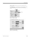
ON/STBY button
This button is theON/STBY
switch in normal operation.
The PRINCIPAL POWER
SWITCH on the rear panel
must be on.
CAUTION
To prevent loss of data and/or damage to the hard
drive, before the power off, be sure to confirm the
floppy disk or hard drive LED is not on or blinking.
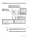
CAUTION
To prevent damage to the instrument, do not apply the
voltage to OUTPUT or MARKER connectors.
Provides normal (CH1) and inverted
(CH1
) waveforms.
The maximum output level is 2
V
pkĆpk
into a 50 W load in Normal
mode, and 1 V
pkĆpk
into a 50 W load
in Direct mode and option 02. If you
use only one output connector, you
must terminate the other connector
using a 50 W termination.
Figure 2-3: Front panel controls