


AWG710 Service Manual
2-1
Preparation for Use
This subsection provides the following information:
H Supplying Operating Power
H Operating Environment
H Installation
H Repackaging Instructions
Supplying Operating Power
WARNING. To avoid equipment failure and potential fire or personal shock
hazards, do not exceed the maximum rated operating voltage of 250 V between
the voltage-to-ground (earth) and either pole of the power source. The AWG710
Arbitrary Waveform Generator operates from a single-phase power source and
has a three-wire power cord with a two-pole, three-terminal grounding plug.
Also, before making a connection to the power source, be sure the AWG710
Arbitrary Waveform Generator has a suitable two-pole, three-terminal ground-
ing-type plug.
To avoid personal shock, do not touch any conductive parts. All accessible
conductive parts are directly connected through the grounding conductor of the
power cord to the grounded (earth) contact of the power plug. The AWG710
Arbitrary Waveform Generator is safety Class 1 equipment (IEC designation).
To prevent electrical shock, remove all power from the instrument, turn the
PRINCIPAL POWER SWITCH on the back panel to OFF, and disconnect the
power cord from the instrument. Some components in the AWG710 Arbitrary
Waveform Generator are still connected to line voltage after toggling the
instrument to Standby from the front panel ON/STBY button.
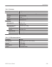
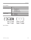
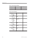
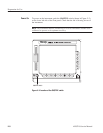
A power cord with the appropriate plug configuration is supplied with each
AWG710 Arbitrary Waveform Generator. Table 2–1 provides color-coding
identification for the power cord conductors. If you require a power cord other
than the one supplied, refer to Table 2–2.
Power Cord Information