


Removal and Installation Procedures
AWG710 Service Manual
6-27
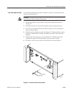
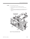
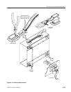
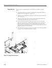
Output assembly
Figure 6-12: Output assembly removal
You will need a pair of needle-nose pliers (Table 6–4, Item 5).
1. Locate the modules to be removed in Figure 6–2, page 6–12.
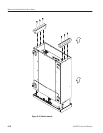
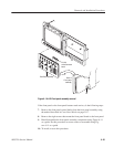
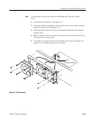
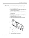
2. Orient the waveform generator so the left side is on the work surface and the
handle is facing upward (see Figure 6–13).
3. Remove the handle by inserting the tips of a pair of needle-nose pliers
(Table 6–4, Item 5) into the hole of either handle cap. Push and hold to
depress the handle release.
4. While holding the handle release, pull it out of the slot in the handle cap.
Repeat the procedure to remove the handle from the other handle cap.
5. To install, reverse this procedure.
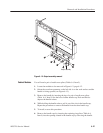
6. Remove the handle caps by inserting the retaining ring pliers (Table 6–4,
Item 9) into the opening created in the handle cap by removing the handle.
Cabinet Modules