


Operating Basics
AWG710 Service Manual
2-45
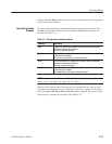
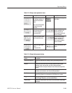
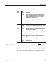
Table 2-15: Setup output parameter operations (cont.)
Bottom
button
Description
Side
button
Horizontal
Clock Sets the clock sample rate from 10 kS/s to 200 MS/s.
Clock Src Sets the clock source to either Internal or External. When set to
Internal, 10 MHz internal reference clock is used. When set to
External, a valid external clock signal is DC to 200 MHz with a
voltage level of 0.4 V
pkĆpk
and up to ±2V.
Clock Ref Sets the reference clock source to either Internal or External. A
valid external clock signal is 10 MHz ±0.1 MHz with a voltage
level of 0.2 V to 3.0 V
pkĆpk
.
Skew... Sets the skew between Ch1, Ch2 and CH3 within -2.52 ns to 2.52
ns with 70 ps steps.
Run Mode Continuous
Triggered
Gated
Enhanced
Displays the Run Mode side menu for setting the instrument run
mode. Refer to the Run Mode Menu subsection on page 3-4 for
an explanation of the different run modes.
Trigger
Source Sets trigger source to Internal or External. If External is selected,
only the interval item is selectable.
Slope Sets the trigger slope or gate polarity to Positive or Negative.
Level Sets the trigger signal level. The trigger level range is ±5.0Vin
0.1 V increments.
Impedance Sets the external trigger input line impedance to either 50 W or
1 kW.
Interval Sets trigger interval from 1.0 ms to 10.0 s.
Save/ReĆ
store
Save Setup Save the setup parameters set by SETUP window as a setup file.
s
t
ore
Restore
Setup
Restore a setup file.
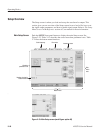
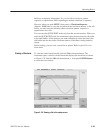
To output a loaded waveform, push the CH (1) OUT and/or CH (1 )_OUT front
panel button(s), and then the front panel RUN button. The LEDs near each
button light to indicate they are enabled. The instrument outputs the waveform(s)
depending on the Run mode. You can turn either or both channel outputs on or
off while the instrument is running by pushing the CH (1) OUT or the
CH (1)
OUT buttons. To stop the waveform output, push the RUN button so that the
LED light turns off.
Outputting a Waveform