Removal and Installation Procedures
AWG710 Service Manual
6-43
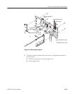
IEEE STD 488 PORT
to J110
10 BASE-T to
the LAN interface
KEYBOARD
to J128
DISPLAY MONITOR OUT
to J127
EVENT IN
to J200
10 MHz REF IN to J130
TRIG IN to J200
10 MHz REF OUT to J150
1/4 CLOCK OUT to J500
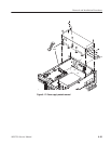
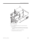
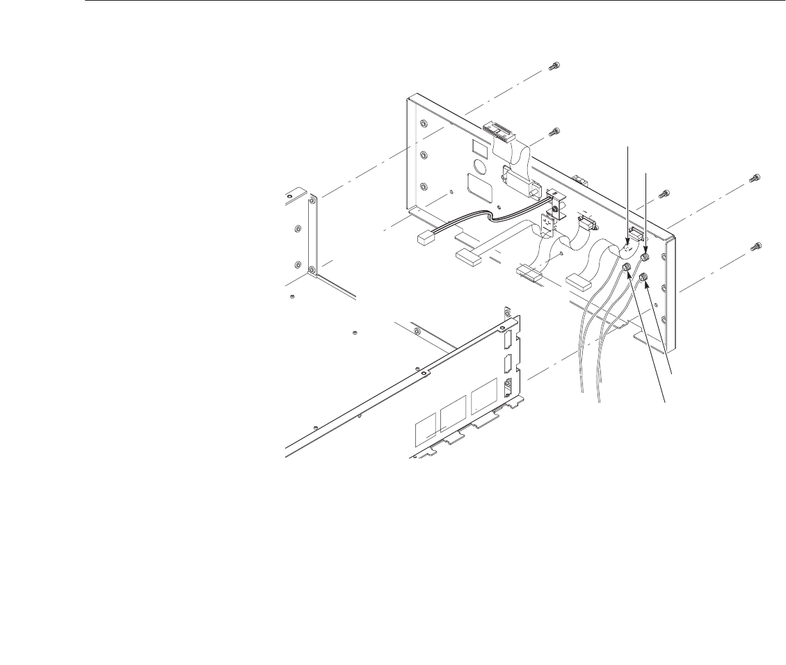
Figure 6-22: Rear chassis removal
6. To install, do this procedure in the reverse order. Complete the assembly in
the order listed.
H PS100 Low Voltage Power Supply (page 6–34)
H Cabinet (page 6–20)


