


Theory of Operation
AWG710 Service Manual
3-5
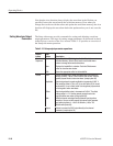
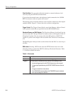
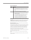
Table 3-1: Run modes (Cont.)
Modes Descriptions
Gated The waveform is output only while:
H An external trigger signal from the TRIG IN connector on the rear panel.
H A gate signal through the FORCE TRIGGER button (on the rear panel) is
TRUE.
H A control command such as trigger or event from remote device.
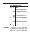
Enhanced The waveform is obtained, in the order defined with the sequence, based on:
H A trigger signal (for example, an external trigger signal from the TRIG IN
connector on the rear panel).
H An external trigger signal from the TRIG IN connector on the rear panel.
H An event signal from the EVENT IN connector on the rear panel.
H An trigger signal from the FORCE TRIGGER button on the front panel.
H An event signal from the FORCE EVENT button on the front panel.
H A control command such as trigger, event or jump from remote device.
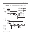
Analog Circuit. The Analog Circuit block contains the Filter, Attenuator, Output
Amplifier, Calibration and Offset Circuits. These circuits are used to process
signals generated from the DAC. Option 02 has Calibration Circuits only.
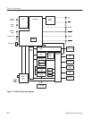
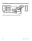
Memory Address Control. The Memory Address Control controls the addresses
used to read waveform memory data.
This block loads the first address of the waveform into the Address Counter that
was loaded into the waveform memory. It loads the waveform data length to the
Length Counter. The Address Counter specifies the point from which the
waveform was generated and the Length Counter waveform ending position.
The Address and Length Counters operate with clocks produced by quarter
frequency-division for the clocks from the clock oscillator.
If the repeat count value has been loaded in the Repeat Counter, the waveform is
generated the specified number of times.
This block controls the sequence to the event signals generated in Enhanced
Mode.
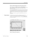
Figure 3–3 shows the relationship between the memory address control and the
waveform memory.