


Removal and Installation Procedures
6-38
AWG710 Service Manual
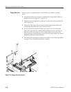
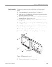
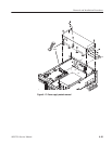
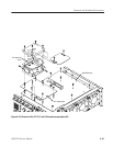
This procedure describes how to remove the following circuit boards that are
contained in the CPU unit:
H CPU board
H Hard Disk and Flash Disk
H A40 PCI Interface Board
H GPIB Board
H Back Plane
NOTE. The Lithium polycarbon monofluoride battery on the CPU board is not
user-replaceable. Removing the battery erases calendar backup data. Replace
the CPU board as a unit. Dispose of the used battery in the proper environmen-
tal manner.
You will need a screwdriver with a size #2
Phillips tip (Table 6–4, Items 1
and 3).
1. Locate the modules to be removed in Figure 6–4, page 6–14.
2. Orient the waveform generator so the bottom is on the work surface and the
right side is facing you.
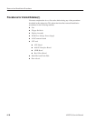
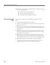
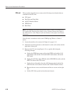
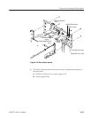
3. Remove the CPU unit using Figure 6–19 as a guide while doing the
following substeps:
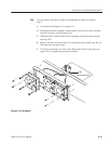
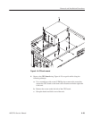
a. Unplug the GPIB interconnect cable at the GPIB board and the LAN
interconnect cable and the VGA and COM1 interconnect cable at the
CPU board.
b. Unplug the LCD flat cable, FDD flat cable, HDD IDE flat cable, and the
MISC flat cable at the CPU board.
c. Unplug the two flat cables from the A50 Sequence board and the flat
cable from the A10 Connector board at the A40 PCI Interface board.
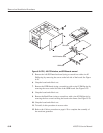
d. Remove the two screws on the bottom and the two screws on the right
side.
e. Lift the CPU Unit up and out from the main chassis.
CPU unit