


Removal and Installation Procedures
AWG710 Service Manual
6-49
You will need a screwdriver with a size #2
Phillips tip (Table 6–4 of page6–10,
Items 1, 3 and 15).
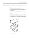
1. Locate the modules to be removed in Figure 6–5, page 6–15.
2. Orient the waveform generator so its top is down on the work surface and its
front is facing you.
3. Unplug the analog output cables with SMA connectors of K100 and K200.
4. Unplug the MKD1 cable with J5400 of the A50 AWG board, the MKD2
cable with J5401.
The MKDx is mentioned in the tip of each cable.
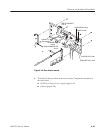
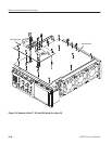
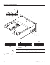
5. Remove the A72 Output board on the post spacer with six-
screws(211–0751–00).
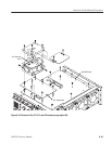
6. Remove the A72 Output Board using Figure 6–24 on page 6–48 as a guide.
7. Lift the A72 Output board up perpendicularly from the A50 AWG board to
complete the removal.
8. To install, do this procedure in the reverse order and proceed to the Cabinet
procedure (page 6–20) to complete the assembly.
A72 Output Board
(option 02 only)