


Removal and Installation Procedures
6-46
AWG710 Service Manual
You will need a screwdriver with a size #2
Phillips tip (Table 6–4, Items 1
and 3).
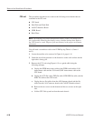
1. Locate the modules to be removed in Figure 6–5, page 6–15.
2. Orient the waveform generator so its top is down on the work surface and its
front is facing you.
3. Perform the A77 Attenuator Board procedure that precedes this procedure to
remove the interconnect cables.
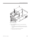
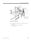
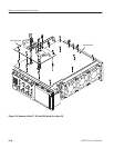
4. Remove the A72 Output Board using Figure 6–23 on page 6–45 as a guide.
5. Unplug the eight cables from the A77 Attenuator Board.
6. Remove the six screws on the front panel and rear panel sides that attach the
A72 Output Board to the A50 AWG board.
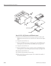
7. Lift the Output board up perpendicularly from the A50 AWG board to
complete the removal.
NOTE. A72 Output Board has a connector on the front panel side, and is
connected with A50 AWG board. In case you remove A72 Output Board, raise
perpendicularly. If the post spacer(s) is removed with the output board, remove
the spacer(s) and screw it back into its mounting hole.
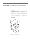
8. To install, do this procedure in the reverse order and proceed to the Cabinet
procedure (page 6–20) to complete the assembly.
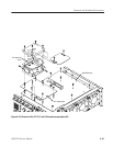
A71 Output Board
(except option 02)