


Performance Verification
4-22
AWG710 Service Manual
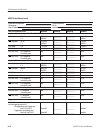
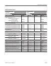
Amplitude and Offset Accuracy Tests (Normal Out), (except option 02)
These procedures check the accuracy of the amplitude and offset outputs of the
AWG710 Arbitrary Waveform Generator.
NOTE. The amplitude and offset accuracy checks are structured as a continuous
test. The next test uses the control settings from the previous test and uses the
next step in the sequence file.
NOTE. When you output signal from the CH1 or CH1
OUTPUT, check that the
other OUTPUT ( CH1
or CH1 ) LED is off.
If the other OUTPUT LED is on, push the CH1
or CH1 OUT button to turn off
the output.
Equipment
required
A 50ĂW BNCĂcoaxial cable, a 50ĂWĂprecision terminator, aĂSMA
(male)ĆBNC (female)Ăadapters, BNC (female)ĆtoĆdual banana adapter,
and a digital multimeter (DMM).
Prerequisites The AWG710 Arbitrary Waveform Generator must meet the
prerequisites listed on page 4-8.
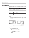
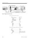
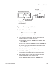
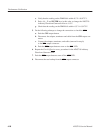
Do the following steps to install the test hookup and set the test equipment
controls:
1. Use a 50 W BNC coaxial cable, a SMA(Ma)-BNC(Fe) adapter, a 50 W
precision terminator, and a BNC-to-dual banana adapter to connect the
AWG710 Arbitrary Waveform Generator CH1 output to the DMM input
connector (see Figure 4–9).
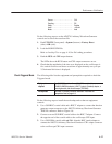
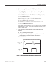
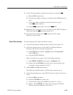
Check Amplitude
Accuracy