


Performance Verification
AWG710 Service Manual
4-49
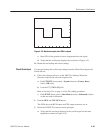
b. Set the function generator (AFG310) controls:
Function . ....................... Square
Mode .......................... Continuous
Parameters
Frequency .................. 10MHz
Amplitude . .................. 2.0Vinto 50 W (4.0 V into 1 MW)
Offset...................... 0V
Output . ........................ On
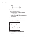
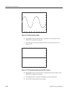
1. Follow the substeps below to set the AWG710 Arbitrary Waveform
Generator controls and select the waveform file:
a. Push UTILITY (front-panel)!System (bottom)!Factory Reset
(side)!OK (side).
b. Load the MODE.WFM file.
Refer to Loading Files on page 4–10 for file loading procedures.
c. Push HORIZONTAL MENU (front-panel)!Clock (side).
d. Push 2, 0, 0 and M (SHIFT+7) keys in this order or turn the general pur-
pose knob to set the internal clock frequency to 200 MHz.
2. Push the RUN button.
The LED above the RUN button is on.
3. Verify that the frequency counter reading is 50 MHz ± 50 Hz (using the
internal reference clock).
4. Retain the test hookup.
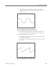
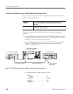
1. Push HORIZONTAL MENU (front-panel)!Clock Ref (side) so that the
AWG710 Arbitrary Waveform Generator reference clock is set to External.
2. Verify that the frequency counter reading is 50.0 MHz ±10 kHz (using the
external reference clock).
3. Change the function generator controls as follows:
Frequency . ..................... 10.1 MHz
4. Check that the frequency counter reading is 50.5 MHz ±10 kHz.
5. Turn the function generator output off and disconnect the function generator
and frequency counter.
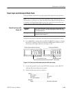
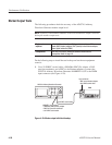
CheckĂ1/4ĂClock
frequency
CheckĂ10MHzĂReference
InputĂ