


Removal and Installation Procedures
6-40
AWG710 Service Manual
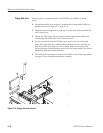
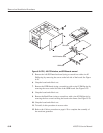
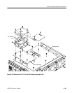
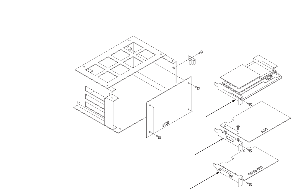
CPU board
A40 PCI Interface board
GPIB board
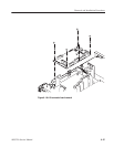
Figure 6-20: CPU, A40 PCI Interface, and GPIB boards removal
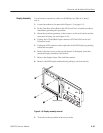
5. Remove the A40 PCI Interface board (using a screwdriver with a size #2
Phillips tip) by removing the screw on the left side of the board. See Figure
6–20.
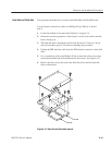
6. Grasp the board and slide it out.
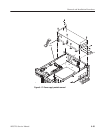
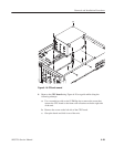
7. Remove the GPIB board (using a screwdriver with a size #2 Phillips tip) by
removing the screw on the left side of the GPIB board. See Figure 6–20.
8. Grasp the board and slide it out.
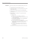
9. Remove the Back Plane (using a screwdriver with a size #2 Phillips tip) by
removing the four screws securing the board to the frame. See Figure 6–20.
10. Grasp the board and slide it out.
11. To install, do this procedure in reverse order.
12. Refer to the Cabinet procedure on page 6–20 to complete the assembly of
the waveform generator.