


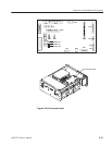
Removal and Installation Procedures
6-52
AWG710 Service Manual
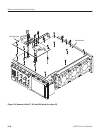
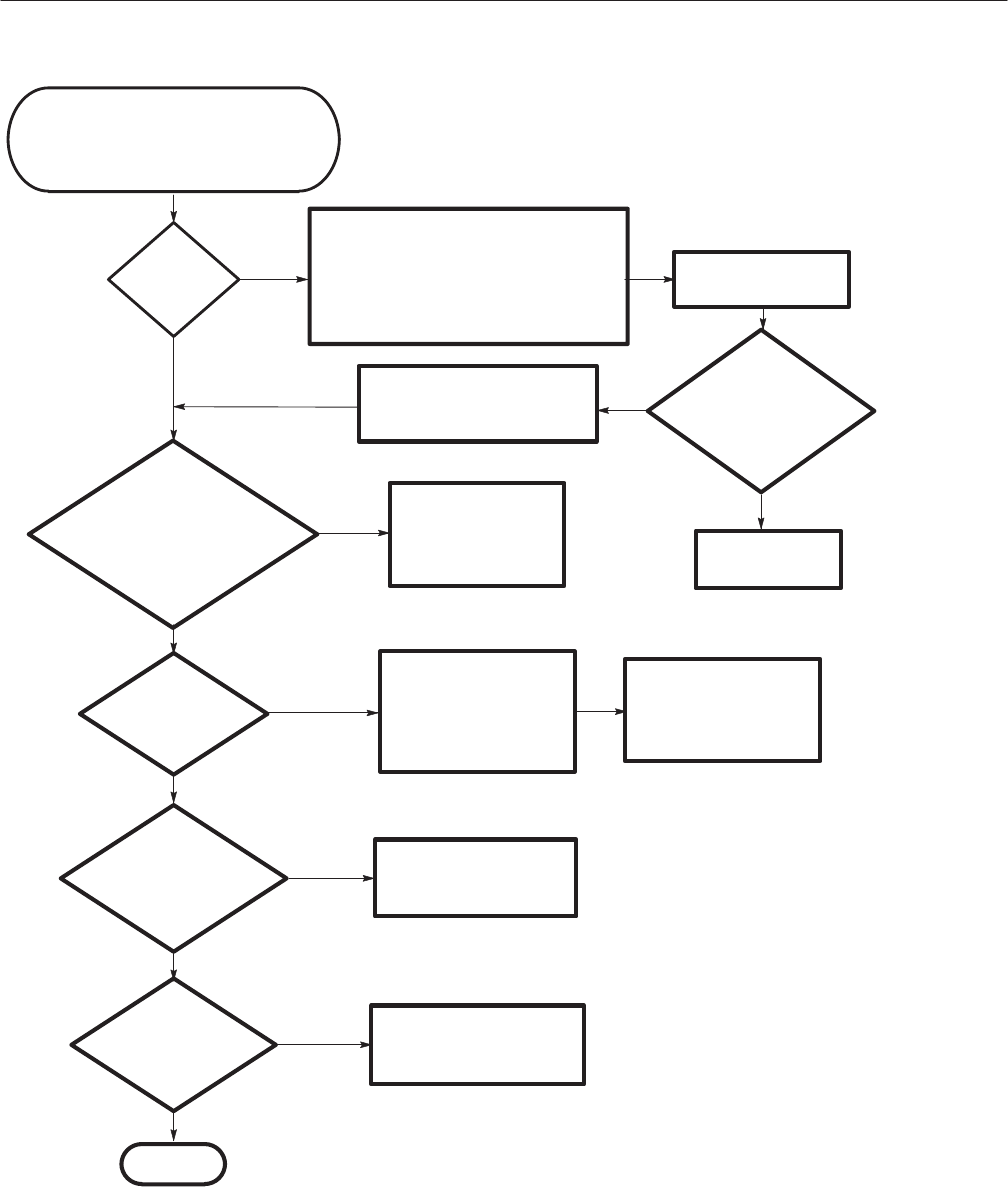
Press the PRINCIPAL POWER SWITCH to
OFF and remove the cover using the Rear
Cover and Cabinet removal procedure. Check
all the cables coming out of the power supply
module and the cabling between modules. Be
sure every cable is attached securely.
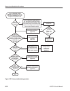
Press the PRINCIPAL POWER
SWITCH on the rear panel to ON, and
then toggle the ON/STBY button on the
front panel of the generator to ON.
Perform the front panel
module troubleshooting
procedure 2
(page 6-55).
With the
generator power on,
do the front panel lights
and PANEL LOCK LED blinks for a
while and go off later (all LED s
except SETUP and
CH1 LED)?
Does the
display seem
to be working
at all?
Press the PRINCIPAL
POWER SWITCH to OFF
and remove the cabinet
using the Rear Cover and
Cabinet removal procedure.
Perform the LCD and
Backlight inverter
troubleshooting
procedure 3
(page 6-33).
Does the
generator respond
correctly when the
front panel buttons
are pushed?
Perform the CPU module
troubleshooting procedure 2
(page 6-55).
Does
the generator power
on and pass all the
diagnostics?
Perform the module isolation
troubleshooting procedure 4
(page 6-31).
Done.
No
Yes
Replace the Fun
(page 6-31).
Is
the voltage on
A10 board
TP030:+5V
TP010 : +12 V
TP020:-5V
?
No
Perform the power supply module
troubleshooting procedure 1
(page 6-53).
Yes
No
Yes
Yes
No
No
Yes
No
Can you
hear the fan
running?
Disconnect the fan cable
and power on.
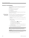
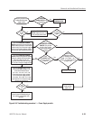
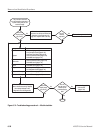
Figure 6-25: Primary troubleshooting procedure