


Removal and Installation Procedures
AWG710 Service Manual
6-53
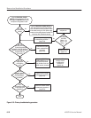
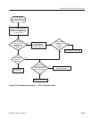
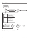
Use this procedure to
troubleshoot the power
supply module.
Is
the PRINCIPAL
POWER SWITCH in the
ON position?
Is
line fuse
ok?
Turn off the PRINCIPAL POWER
SWITCH. Replace the fuse. Turn
on the principal power switch.
Fix the power problem.
Replace the power
supply module
(page 6-34).
Yes
Yes
No
Turn on the PRINCIPAL
POWER SWITCH.
Does
the fuse blow
again?
No
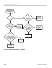
Turn off the PRINCIPAL POWER
SWITCH and remove the cover using the
Cabinet removal procedure. Check all the
cables coming out of the power supply
module and the cabling between modules.
Be sure every cable is attached securely.
No
Yes
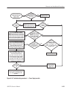
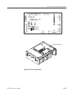
Are the
voltages on the
A11 Connector board
TP030 : +5 V, TP010 : +12 V
TP030 : -5 V (see Figure 6-30
on page 6-57)?
Press
the ON/STBY button.
Does the generator
power on?
Turn on
the PRINCIPAL POWER
SWITCH. Can you hear
the tick of relay actuator
in the power supply
module?
Turn off the PRINCIPAL POWER
SWITCH. Remove the generator cabinet
using the cabinet removal procedure.
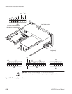
Check the cables from the A11
Connector board. Disconnect the cables
at J1 and J2 on the power supply module.
Yes
Press the ON/STBY button. Check
these power supply voltages on J3
on the A10 Connector board:
+5 V"3%, -5 V"5%, +12 V"5%.
Check these power supply voltages
on J2 on the power supply module:
-2 V"20%, -8 V"20%, +8 V"20%
(see Figure 6-27 for the power supply
connector pin assignment).
Are
the voltages
ok?
The power supply module is ok.
Perform isolation troubleshooting for
the modules on the bottom of the
generator.
Yes
No
Yes
No
No
No
Yes
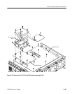
Figure 6-26: Troubleshooting procedure 1 Ċ Power Supply module