


Performance Verification
4-44
AWG710 Service Manual
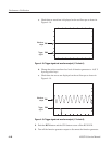
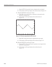
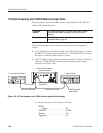
c. Open the SW2 of the ground closure to degenerate the event signal.
d. Verify that the oscilloscope displays the waveform shown in Figure 4–21.
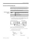
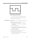
9. Check the EVENT IN connector pin 2 input:
a. Close SW3 of the ground closure to generate an event signal on the
EVENT IN connector pin 2.
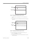
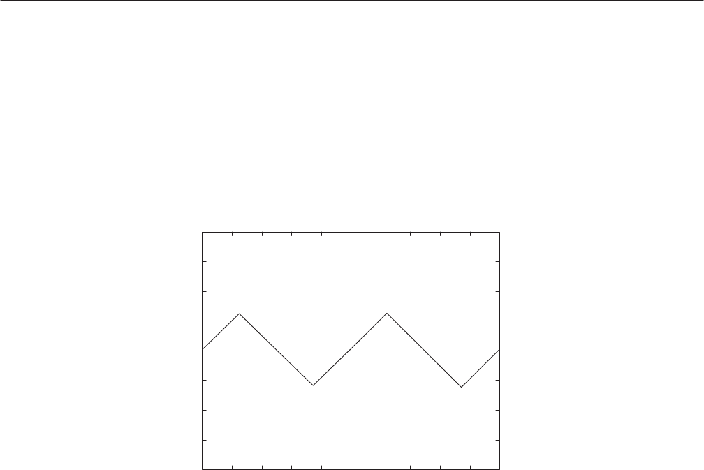
b. Verify that the oscilloscope displays the waveform shown in
Figure 4–24.
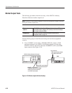
Figure 4-24: Waveform output when the SW3 is closed
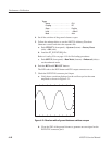
c. Open SW3 of the ground closure to degenerate the event signal.
d. Verify that the oscilloscope displays the waveform in Figure 4–21.
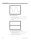
10. Check the EVENT IN connector pin 3 input:
a. Close the SW4 of the ground closure to generate an event signal on the
EVENT IN connector pin 3.
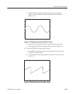
b. Verify that the oscilloscope displays the waveform shown in
Figure 4–25.