


Removal and Installation Procedures
6-24
AWG710 Service Manual
CAUTION. To prevent damage to the contacts, do not touch the carbon contact
points on the menu buttons installed in the trim ring. Also, do not touch the
contacts on the exposed flex circuit when you remove the trim ring.
4. Remove the trim ring by grasping the top edge and prying it up and lifting it
forward to snap it off the front subpanel. If servicing the menu buttons, lift
them out of the trim ring. When installing, insert the menu buttons, align the
trim ring to the front subpanel and press it back on.
5. To install the output panel, menu buttons, and trim ring, do step 3 and step 4
in reverse order.
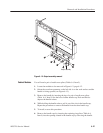
This procedure includes removal and installation instructions for the front panel
and front panel buttons. Unless either of those modules are being serviced, do
not do step 4.
You will need a screwdriver with a size Phillips #2
tip (Table 6–4, Items 1
and 3).
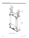
1. Locate the modules to be removed in Figure 6–2, page 6–12.
2. Do the procedure Trim Ring step 1 through step 5, before proceeding to step
3 of this procedure.
3. Orient the waveform generator so the bottom is on the work surface and the
front is facing you.
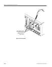
4. Remove the front panel assembly from the front subpanel by lifting the
assembly until you can reach the interconnect cable connecting to the
Connector board.
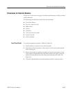
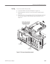
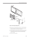
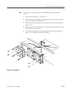
5. Disconnect the cable at J154 of the Connector board. Disconnect the
flex-board connector at P3 of the front panel assembly. (The flex board is
part of the display-frame assembly.) See Figure 6–10.
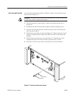
6. Lift the front panel assembly out of the front subpanel to complete the
assembly.
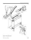
A20 Front Panel Assembly