


Removal and Installation Procedures
6-36
AWG710 Service Manual
You will need a screwdriver with a size #2
Phillips tip (Table 6–4, Items 1
and 3).
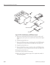
1. Locate the modules to be removed in Figure 6–3, page 6–13.
2. Orient the waveform generator so the bottom is on the work surface and the
front is facing you.
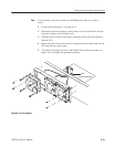
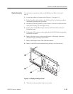
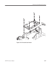
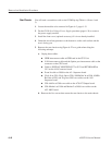
3. To disconnect the A10 Connector board, disconnect the following cables and
connectors. See Figure 6–18 as a guide.
H Fan power cable at J310
H Cable from the low–voltage power supply at J010
H Cable to the PCI Backplane power supply at J320
H J245 LCD Backlight, J225 TFT LCD and J102 Floppy disk driver
connector
H Interconnect cables from CPU board at J100 CPU FDD, J110 CPU
MISC, J150 CPU VGA & COM1 and J220 CPU LCD
H Interconnect cables to the Monitor Out at J152 and the A90 Key
board at J112
H Interconnect cable from the PCI Interface at 200
H Cables from the A20 Front Panel board at J154
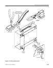
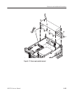
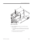
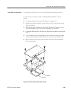
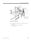
4. Use a screwdriver with a size #2 Phillips tip to remove the five screws that
attach the A11 Connector board to the HDD bracket.
5. Lift the board up and out from the HDD bracket to complete the removal.
6. To install, do this procedure in reverse order. Refer to the Cabinet procedure
on page 6–20 to complete the assembly of the generator.
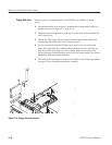
A10 Connector Board