


Theory of Operation
AWG710 Service Manual
3-3
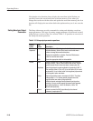
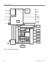
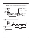
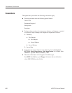
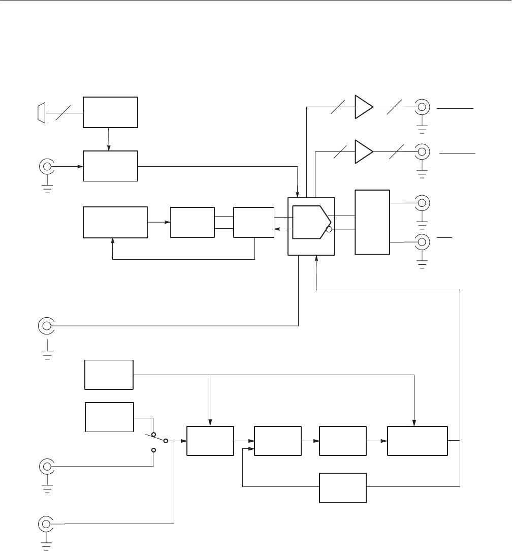
Figure 3–2 shows the main hardware blocks that comprise the AWG710
Arbitrary Waveform Generator.
ĂĂĂĂĂVCO
EXTĂREF
CLOCK
(10ĂMHz)
1/4
CLOCK
OUT
EXT
TRIG
ĂIN
EXT
EVENT
IN
Event control
Memory
address control
Analog
output
circuit
CH1
CH1
MARKER1
MARKER1
22
4
DAC
Waveform
Ămemory
Shift
register
REF
CLOCK
OUT
(10ĂMHz)
Trigger
control
MARKER2
MARKER2
22
Frequency
control
Reference
oscillator
Clock
output
Loop
filter
DDS
Phase
comparator
1/2048
ĂDivider
DAC ASIC
Figure 3-2: AWG710 block diagram
Block Diagram