


Performance Verification
AWG710 Service Manual
4-51
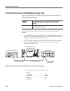
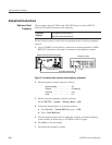
2. Set the DMM controls as follows:
Mode . ......................... VDC
Range ......................... Auto
Input .......................... Front
3. Follow the substeps below to set the AWG710 Arbitrary Waveform
Generator controls and to select the sequence file:
a. Push UTILITY (front-panel)!System (bottom)!Factory Reset
(side)!OK (side).
b. Push SETUP (front-panel)!Run Mode (bottom)!Enhanced (side).
The AWG710 Arbitrary Waveform Generator is set to enhanced mode.
c. Load the AMP1.SEQ file.
Refer to Loading Files on page 4–10 for file loading procedures.
4. Push the RUN button.
The LEDs above the RUN button is on.
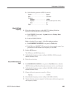
5. Do the following substeps to set the AWG710 Arbitrary Waveform
Generator marker output high level setting:
a. Push VERTICAL MENU (front-panel)!Marker... (side)!Marker 1
High Level (side).
b. Push 3, ., 0 and ENTER keys in this order or turn the general pur-
pose knob to set the marker level to 3.0 V.
c. Verify that the marker 1 high level reading on the DMM screen falls
within 2.75 V through 3.25 V.
d. Push the FORCE EVENT button.
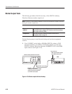
6. Do the following substeps to set the AWG710 Arbitrary Waveform
Generator marker output low level setting:
a. Push Marker 1 Low Level side button.
b. Push –, 1, ., 1 and ENTER keys in this order or turn the general pur-
pose knob to set the marker level to –1.1 V.
c. Verify that the marker 1 Low level reading on the DMM screen falls
within –1.255 V through –0.945 V.
d. Push the FORCE EVENT button.