


Operating Basics
AWG710 Service Manual
2-41
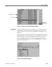
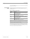
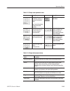
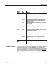
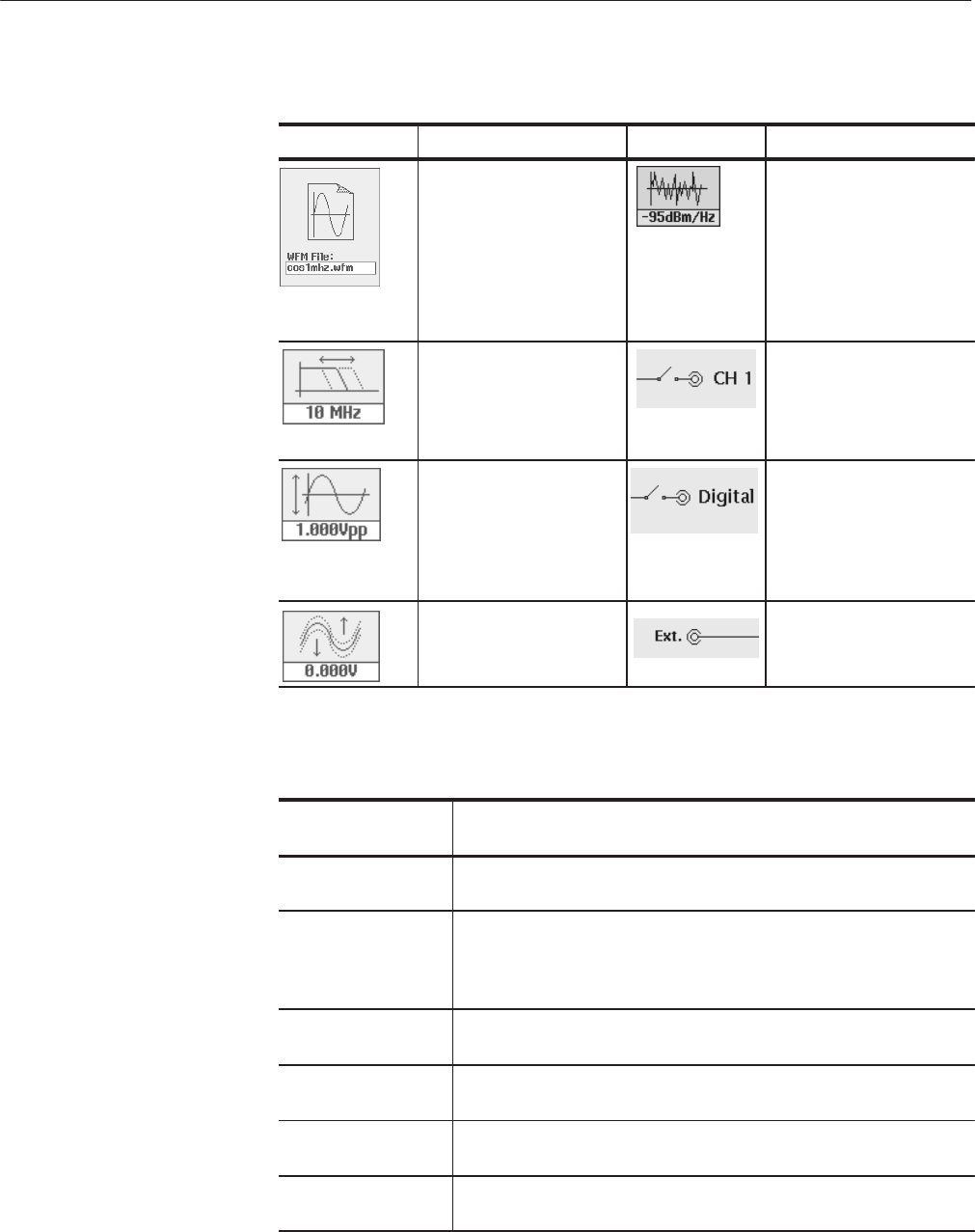
Table 2-13: Setup screen parameter icons
Icon Description Icon Description
Displays the file name of
the waveform, pattern, or
sequence file loaded for
output.
Note: Use the View button
to display the loaded
waveform.
Displays the noise signal
level added.
Displays the lowĆpass filter
setting through which the
waveform is passed.
(except option 02)
Indicates that the channel
output is enabled or disĆ
abled. If the switch is
shown open, that channel
output is disabled.
Displays the peakĆtoĆpeak
signal amplitude setting.
Indicates that the digital
output is enabled or disĆ
abled. If the switch is
shown open, that digital
output is disabled.
Displays the signal offset
setting.
(except option 02)
Displays the external input
added.
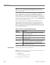
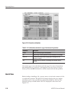
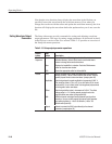
Table 2-14: Setup bottom menu buttons
Bottom menu
button
Description
Waveform/Sequence Displays the side menu for loading, viewing, and editing waveform
files.
Vertical Displays the Vertical side menu for setting waveform peakĆtoĆpeak
amplitude, offset, lowĆpass filter, and other output parameters.
The product which has option 02 doesn't have offset and lowpass filter
function.
Horizontal Displays the Horizontal side menu for setting the clock source, clock
frequency, clock reference, and channel skew parameters.
Run Mode Displays the Run Mode side menu for setting the instrument run mode.
Refer to Run Modes for an explanation of the different run modes.
Trigger Displays the Trigger side menu for setting trigger source, slope, level,
external trigger impedance, and interval parameters.
Save/Restore Displays the Save/Restore side menu to save and restore setup output
parameters.