


Specifications
AWG710 Service Manual
1-7
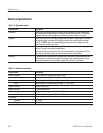
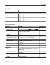
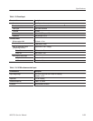
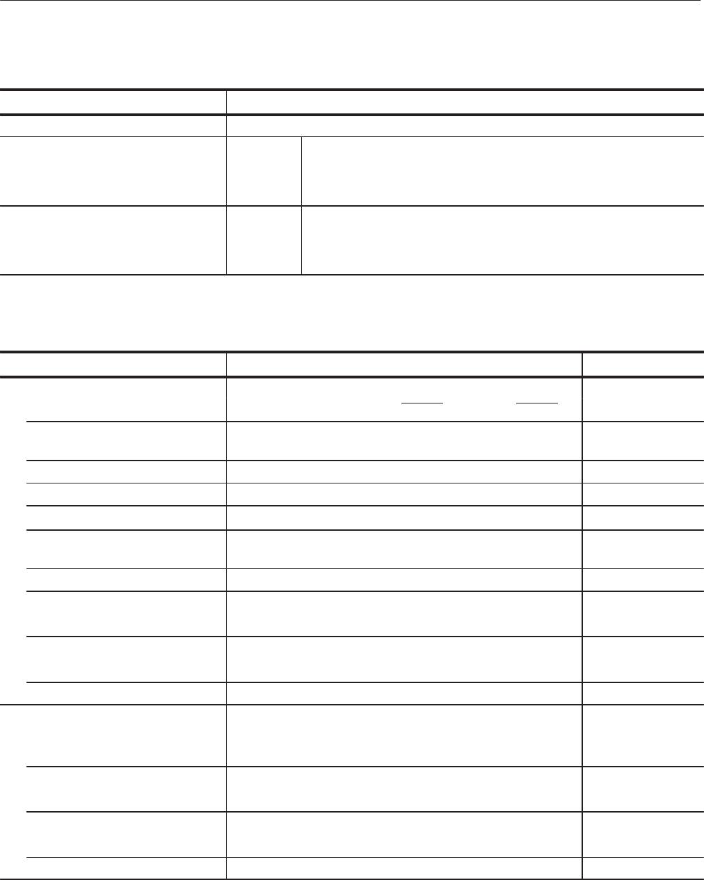
Table 1-7: Filter
Characteristics Description
Type Bessel low pass filter, 200 MHz,100 MHz, 50 MHz, and 20 MHz
Rise time (10% to 90%), Typical 20 MHz
50 MHz
100 MHz
200 MHz
17 ns
7ns
3.7 ns
2ns
Group delay, Typical 20 MHz
50 MHz
100 MHz
200 MHz
18 ns
8ns
4.7 ns
3ns
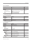
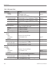
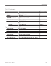
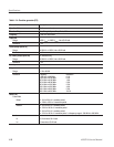
Table 1-8: Auxiliary outputs
Characteristics Description PV reference page
Marker
4
Number of markers 2 (Complementary). Marker1 and Marker1, Marker2 and Marker2
Level (Hi/Lo) -1.10 V to +3.00 V, into a 50 W load
-2.20 V to +6.00 V, intoa1MW load
Maximum Output 2.5 V
pkĆpk
,intoa50W load
Resolution 0.05 V
n Accuracy
"0.1 V "5 % of setting, into a 50 W load
Page 4-50
Rise and fall times (20% to 80%),
Typical
150 ps (2 V
pkĆpk
, Hi: +1 V, Lo: -1 V, into a 50 W load)
Skew, Typical 70 ps
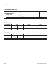
Period jitter, Typical Measured by TDS694C-1MHD with TDSJIT1
Refer to Table 1-9.
Cycle to cycle jitter, Typical Measured by TDS694C-1MHD with TDSJIT1
Refer to Table 1-10.
Connector Front panel SMA connectors
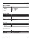
1/4 Clock output
Level ECL 100 K compatible (internally loaded in 50 W to -2 V and 47 W
series terminated)
Period jitter, Typical Measured by TDS694C-1MHD with TDSJIT1
Refer to Table 1-9.
Cycle to cycle jitter, Typical Measured by TDS694C-1MHD with TDSJIT1
Refer to Table 1-10.
Connector Rear panel SMA connector