Contents
©
National Instruments Corporation xi NI-DAQ FRM for PC Compatibles
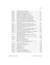
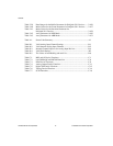
Table 2-1. Parameter Settings for AI_Configure......................................................2-7
Table 2-2. Port 0 Digital I/O Lines Reserved...........................................................2-11
Table 2-3. Reglitching Parameters for Permissible Devices ....................................2-28
Table 2-4. Voltage or Current Output Parameters....................................................2-29
Table 2-5. Parameter Values for FIFO Transfer Conditions....................................2-29
Table 2-6. Default Values for FIFO Transfer Condition..........................................2-30
Table 2-7. Parameter Setting Information for the Analog Filter ..............................2-31
Table 2-8. Parameter Setting Information for the Digital Filter...............................2-31
Table 2-9. Parameter Setting Information for Output Enable ..................................2-32
Table 2-10. Parameter Setting Information for Output Impedance............................2-32
Table 2-11. Parameter Setting Information for Output Attenuation...........................2-33
Table 2-12. Parameter Setting Information for Frequency Correction for
the Analog Filter......................................................................................2-34
Table 2-13. Parameter Setting Information for the Trigger Mode .............................2-35
Table 2-14. Parameter Setting Information for PLL Reference Frequency ...............2-35
Table 2-15. Parameter Setting Information for the SYNC Duty Cycle......................2-36
Table 2-16. Possible Calibrate_1200 Parameter Values.............................................2-51
Table 2-17. DAQEvent Messages ..............................................................................2-74
Table 2-18. Valid Counters and External Timing Signals for DAQEvent = 9...........2-78
Table 2-19. Usable Parameters for Different DAQ Events Codes .............................2-79
Table 2-20. Legal Values for gpctrNum Parameter....................................................2-199
Table 2-21. Legal Values for paramValue when paramID = ND_SOURCE.............2-199
Table 2-22. Definition of Other Counter for paramValue Set to
ND_OTHER_GPCTR_TC......................................................................2-200
Table 2-23. Default Source Selection for ND_SIMPLE_EVENT_CNT or
ND_BUFFERED_EVENT_CNT............................................................2-200
Table 2-24. Legal Values for paramValue when paramID = ND_GATE..................2-203
Table 2-25. Default Gate Selection.............................................................................2-204
Table 2-26. Default Second Gate Selection................................................................2-205
Table 2-27. Legal Values for paramValue when
paramID = ND_INITIAL_COUNT ........................................................2-206
Table 2-28. Legal Values for paramValue when paramID =
ND_COUNT_1,
ND_COUNT_2, ND_COUNT_3, and ND_COUNT_4 .....................................2-206
Table 2-29. Default Up/Down Selection ....................................................................2-207
Table 2-30. Legal Values for the action Parameter....................................................2-211
Table 2-31. Descriptions for application ....................................................................2-216
Table 2-32. Terminal Count........................................................................................2-218
Table 2-33. SCXI Module Scan List ..........................................................................2-348
Table 2-34. MIO or AI Scan List................................................................................2-348
Table 2-35. Possible Values for signal .......................................................................2-374
Table 2-36. Legal Parameters for the 6602 Devices...................................................2-385
Table 2-37. E Series Signal Name Equivalencies.......................................................2-387
Table 2-38. RTSI Bus Line and VXIbus Trigger Mapping........................................2-387


