


Chapter 2 Function Reference — CTR_Config
©
National Instruments Corporation 2-91 NI-DAQ FRM for PC Compatibles
6: Active high on gate of next higher-order counter.
7: Active high on gate of next lower-order counter.
8: Special gating.
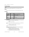
outType selects which type of output is to be generated by the counter. The counters generate
two types of output signals: TC toggled output and TC pulse output.
0: TC toggled output type used.
1: TC pulse output type used.
outPolarity selects the output polarity used by the counter.
0: Positive logic output.
1: Negative logic (inverted) output.
Using This Function
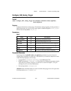
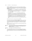
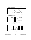
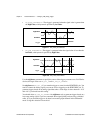
If you select TC pulse output type, outPolarity = 0 means that NI-DAQ generates active
logic-high terminal count pulses. outPolarity = 1 means that NI-DAQ generates active
logic-low terminal count pulses. Similarly, if you select TC toggled output type, then
outPolarity = 0 means the OUT signal toggles from low to high on the first TC. outPolarity
= 1 means the OUT signal toggles from high to low on the first TC.
CTR_Config saves the parameters in the configuration table for the specified counter.
NI-DAQ uses this configuration table when the counter is set up for an event-counting, pulse
output, or frequency output operation. You can use
CTR_Config to take advantage of the
many counter modes.
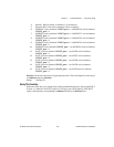
The default settings for the counter configuration modes are as follows:
edgeMode = 0: Counter counts rising edges.
gateMode = 0: No gating used.
outType = 0: TC toggled output type used.
outPolarity = 0: Positive logic output used.
To change the counter configuration from this default setting, you must call
CTR_Config and
indicate which configuration you want before initiating any other counter operation.
Counter configuration settings applied through this function persist when waveform
generation functions use the same counter. For example, to externally trigger a waveform
generation option, use this function to change the gatemode to 1 (high-level gating), and then
call the waveform generation functions. The waveform generation is delayed until a
high-level signal appears on the gate pin on the I/O connector. Notice that this is really not a
trigger signal but is a gating signal, as the waveform generation pauses if the gate goes low at
any time. Because the Am9513 counter/timer chip has certain limitations, you cannot use
gateModes 3 and 4. You are responsible for producing a signal that stays high for the duration
of the waveform generation operation.